
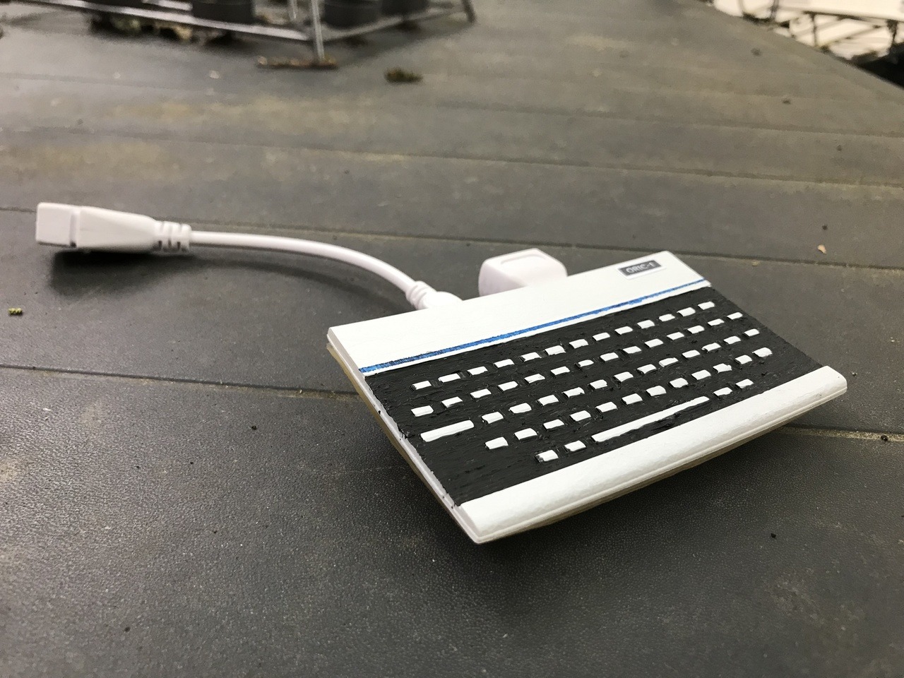
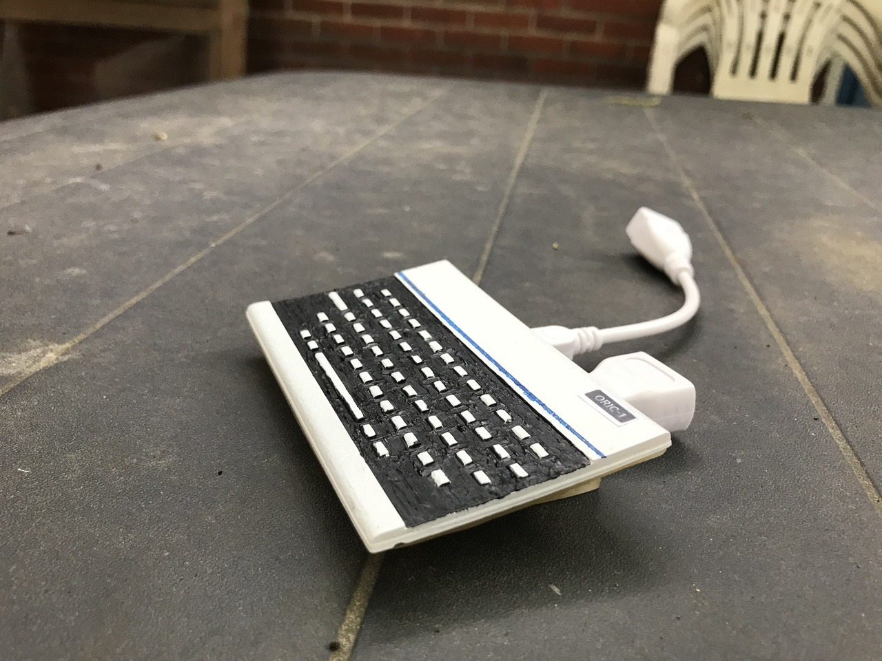
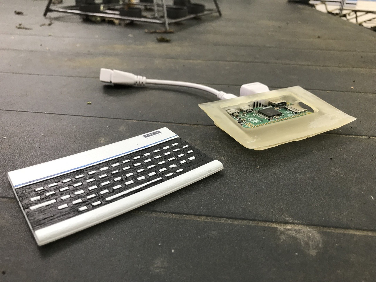
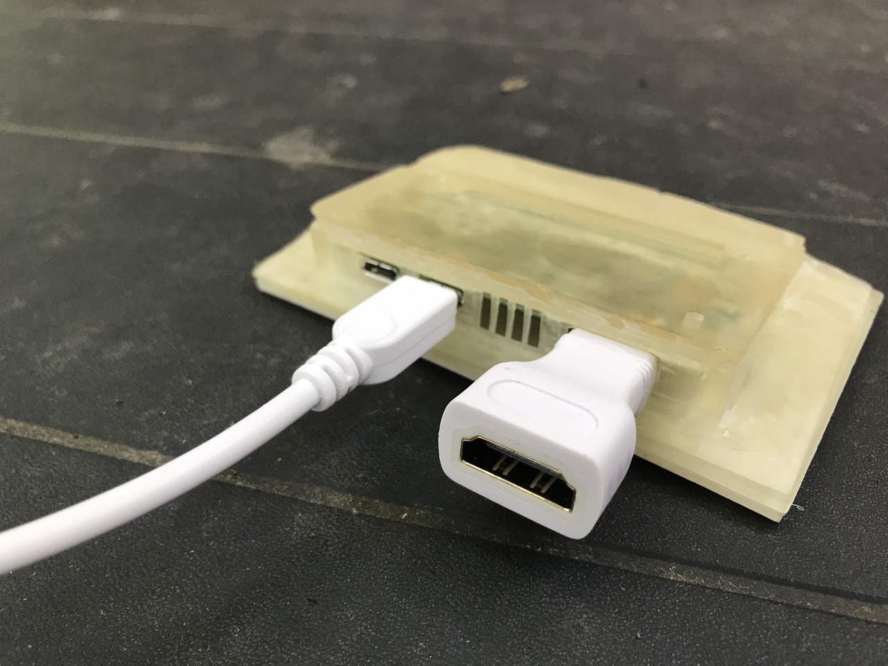
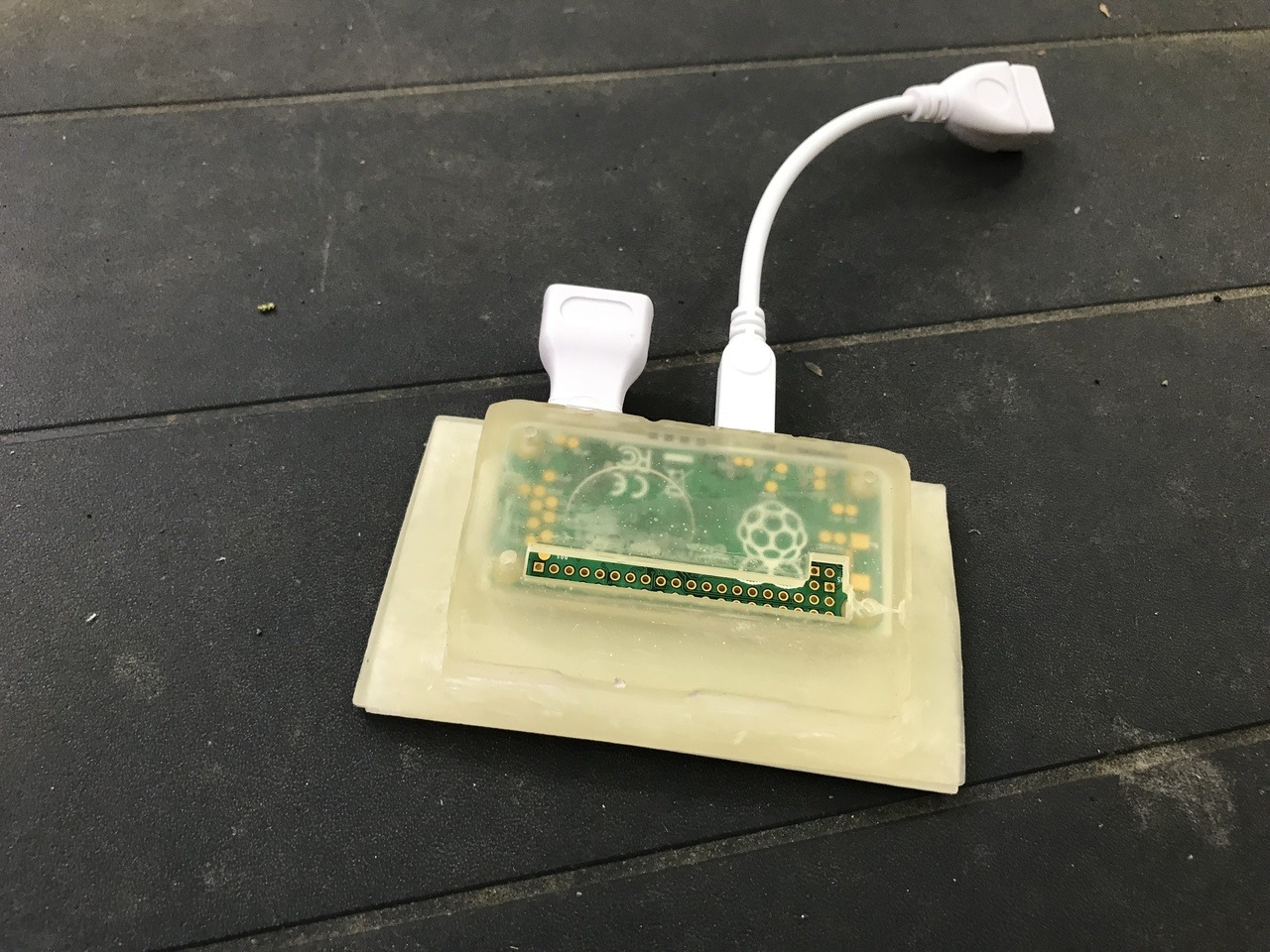
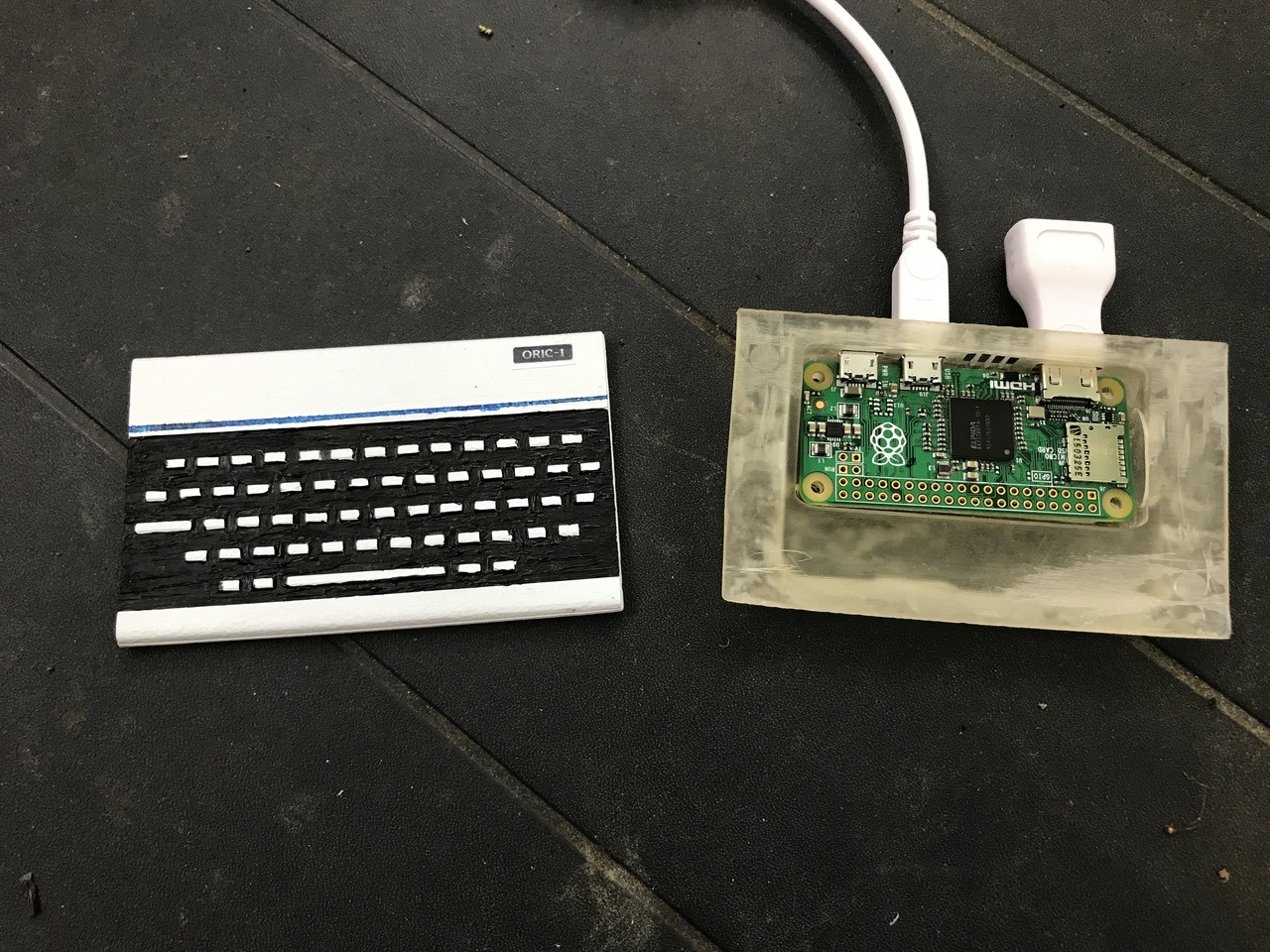
Printed the model and painted it in the original colors.
Print the logo label and stick it on using glue.

If you want the print ready package

Today I finished the install of Xlink Kai on Raspberry Pi.
There were a few things that made the install not that easy.
First of my user name was not ready did’t use the account that much so the email address was not correct.
Apparently it was linkt to my first email address that i own around 1998 till 2003 forgot that I got that 😀
After sorting that out with CrunchBite I could start on this project.
I installed it on my last available Raspberry a first gen. (Raspberry pi 1 B) 😀
So I Downloaded the newest and greatest version.
From the Xlink website.
Or ssh in to your Pi and use curl to download direct to the Pi
curl https://cdn.teamxlink.co.uk/binary/kaiEngine-7.4.33-rev767.headless.ARM.tar.gz --output kaiEngine-7.4.33-rev767.headless.ARM.tar.gz
Then extract it:
tar -zxvf kaiEngine-7.4.33-rev767.headless.ARM.tar.gz

x kaiEngine-7.4.33/

x kaiEngine-7.4.33/runforever.sh

x kaiEngine-7.4.33/kaiengine_arm

x kaiEngine-7.4.33/README
Then a sudo ./kaiengine_arm to test it:
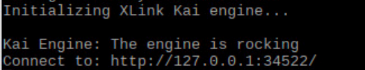
Open a browser and load the ip of your pi + port (http://192.168.1.xxx:34522/)
Then check > Metrics
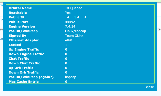
Remember de Public port (44492) you will need it later.
If everything is working like it should you can make it auto boot edit
sudo nano /etc/rc.local
and added sudo screen -DmS kaiengine /home/pi/launchkai.sh above the exit line
After this your almost ready, because there needs to be some port forwarding (for me I did and have upnp on) :
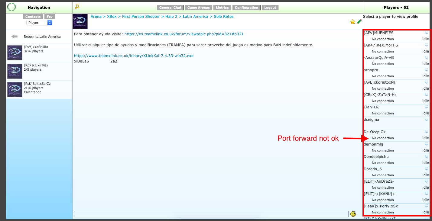
When you join a room and nobody got a connection, this is mostly because the port that is need is not open.
the UI is on port 34522 but we don’t need this outside our house.
I did enabled Pat because I have 1 public ip and more xbox’s
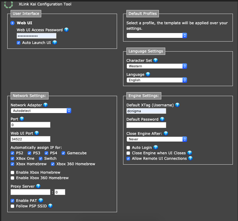
but the public port in my case is 44492 (Remember Metrics) so after changing this in my router:

I get everybody connected and see also ping status. 😀
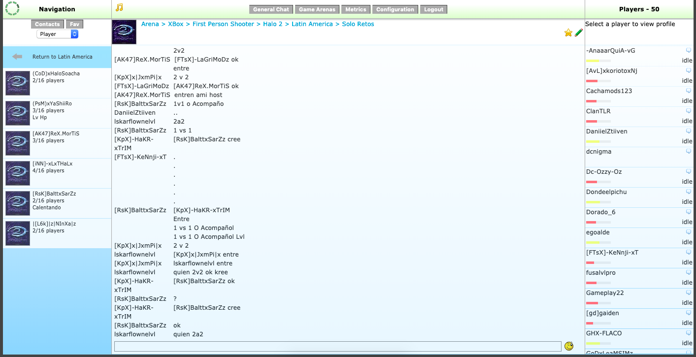
So after that, boot up Halo 2.
![]()
And after selecting System Link a got a lot of games to join:
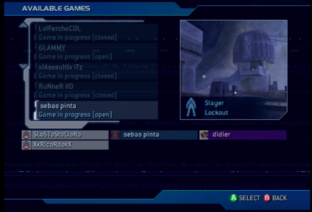
No lets get my ass kick by some PRO halo players 😀

Outcome: Dcnigma 1 other player 20 😛 😛 Omg I need to practice < 🙂

Xlink Kai works perfect and is nice add-on for my xbox’s need to test other consoles later.
 Also i found a little bug:
if your password is contains a = symbol this will break auto login.
When you save your password in the config it will cut your password.
There is a DISCORD INVITE
https://discord.gg/mj44JWy
Now all my Raspberry Pi’s have a purpose.
It’s time that the Raspberry Pi Foundation release a new pi 😀
I probably would get Kai running along DreamPi
but thats something I will test later.
Back to some Halo 2

 Today it was father’s day and I wanted to make something special for my dad.
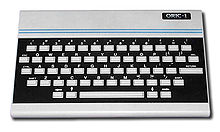
Load that model in to ThinkerCad and a Raspberry Pi zero model, just for size’s.
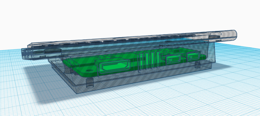
If you want to tinker more:
https://www.tinkercad.com/things/5aVdkiqgLMc-oric-raspberry-pi-zero-w
Added retropie installed the Oric emulator and added the roms.
Oric Atmos theme that i made for the Nes-mini theme:
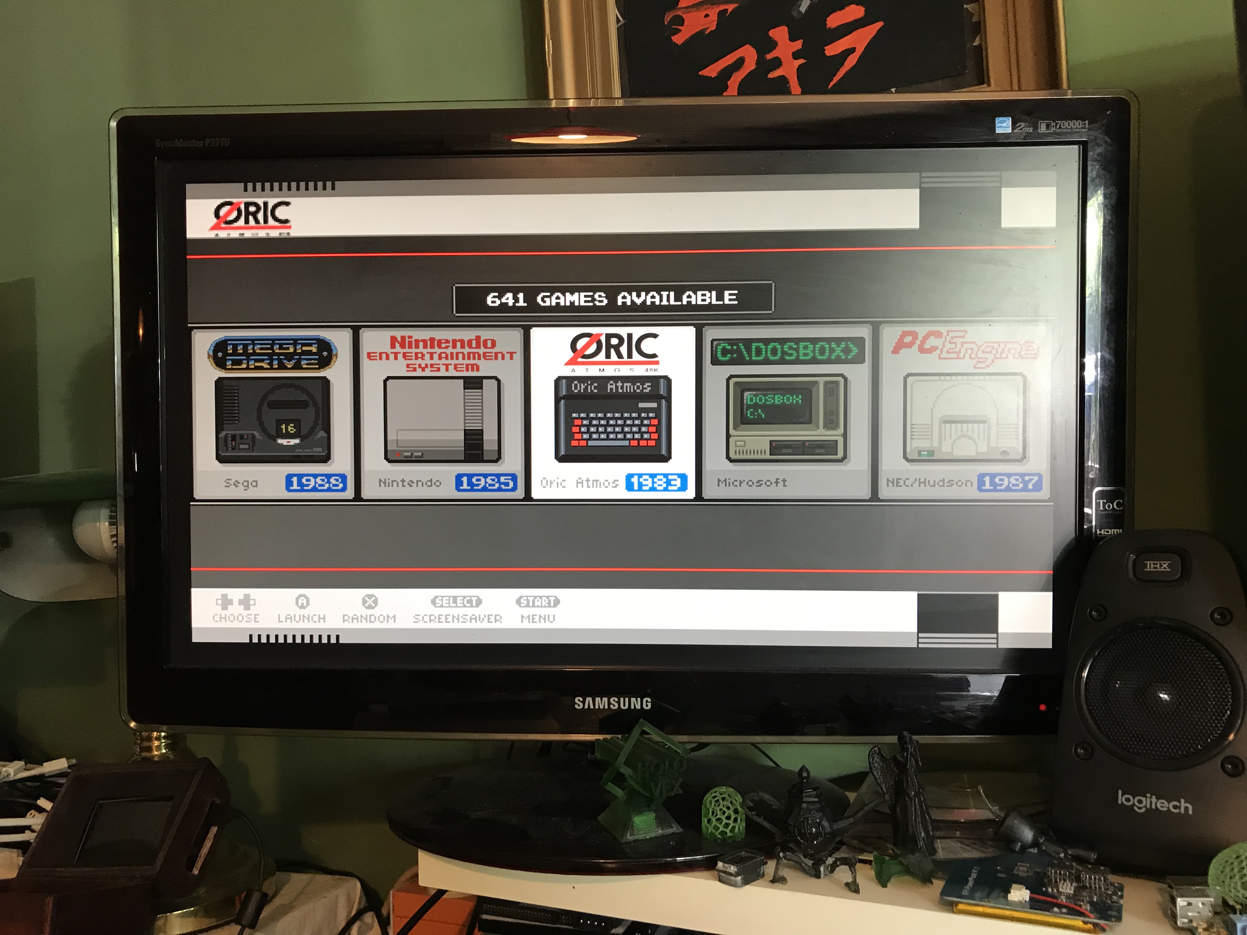
Download link: Oric Atoms. (oops include the psd.. systembackground.png is a psd)
Location of the themes: /etc/emulationstation/themes/(nes-mini)
My dad/mom loved The Oric 1 mini 😀
If you want the print ready package
For awhile I have been trying to make a GAMEBOY and Raspberry Pi Mod.
My last post showing some real progress and installation of the software.
Today I will write a better guide for myself and others so they can learn from my mistakes.
If you follow this guide for setting up your SD cart this progress will take about 1,5 h to complete.
(guide is below show and tell 🙂 )
Warning: I still have to remove a error that i getting but i din’t find a solution for this atm:
”At random times i get: alsa lib pcm.c 7843: (snd_pcm_recover) underrun occurred”
not when playing a game only if i am in the front end and during boot….
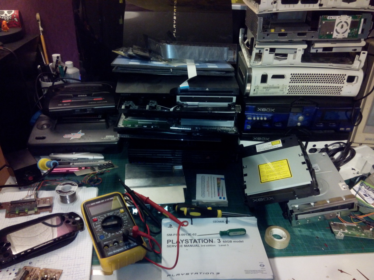
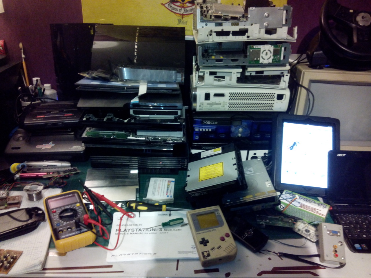
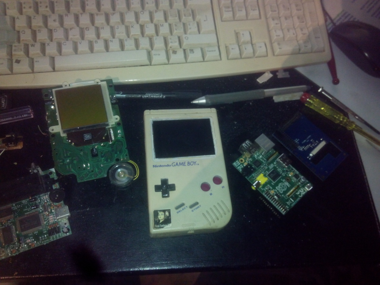
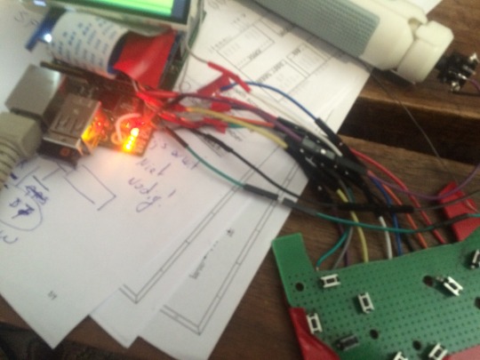
Lets start with show and tell:
Hardware used:
Gameboy case, wires, tact switches, empty PCB, power bar, cheap speakers and a Dremel
And of course a
Raspberry 1b:
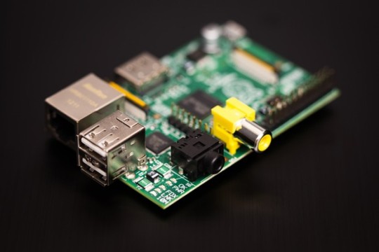
| 000f | Q4 2012 | B | 2.0 | 512 MB | (Mfg by Qisda) |
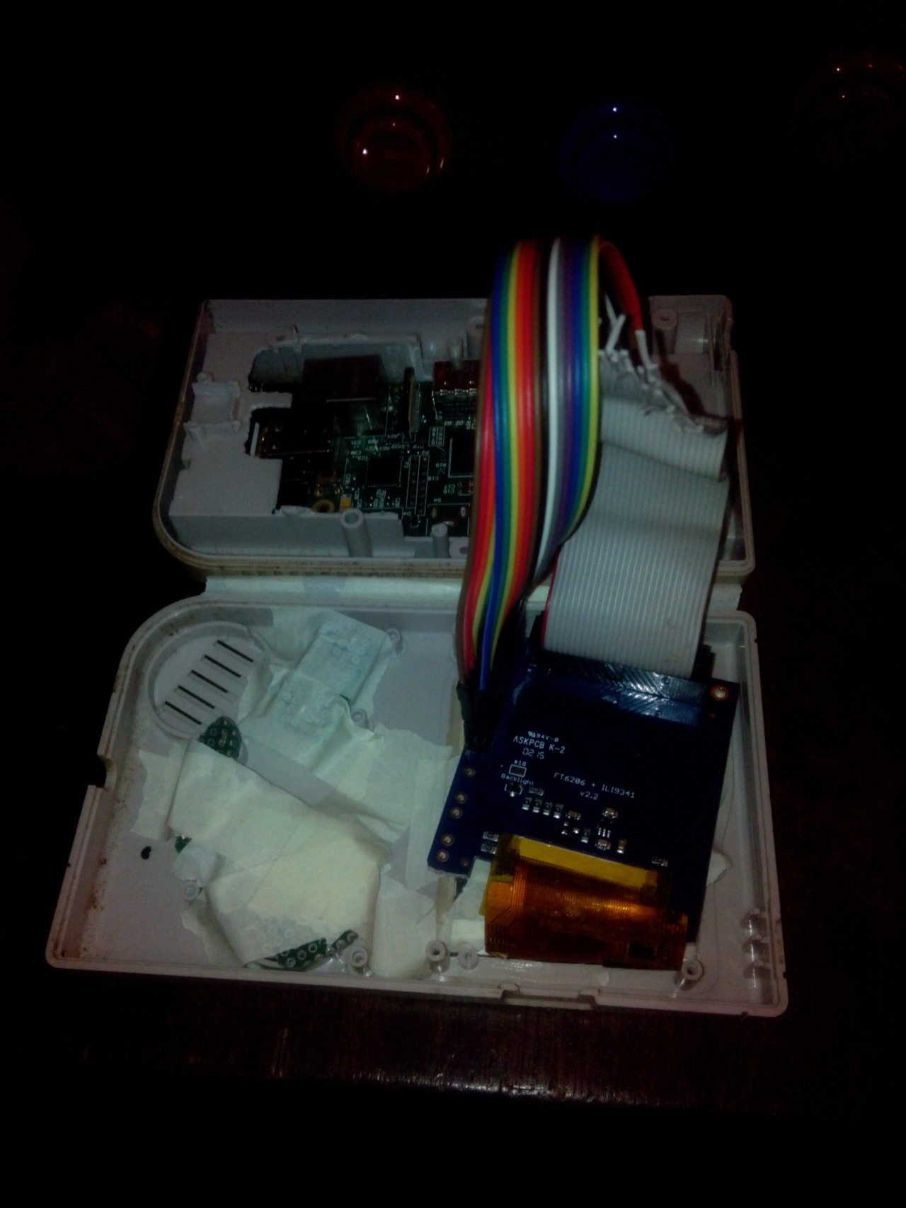
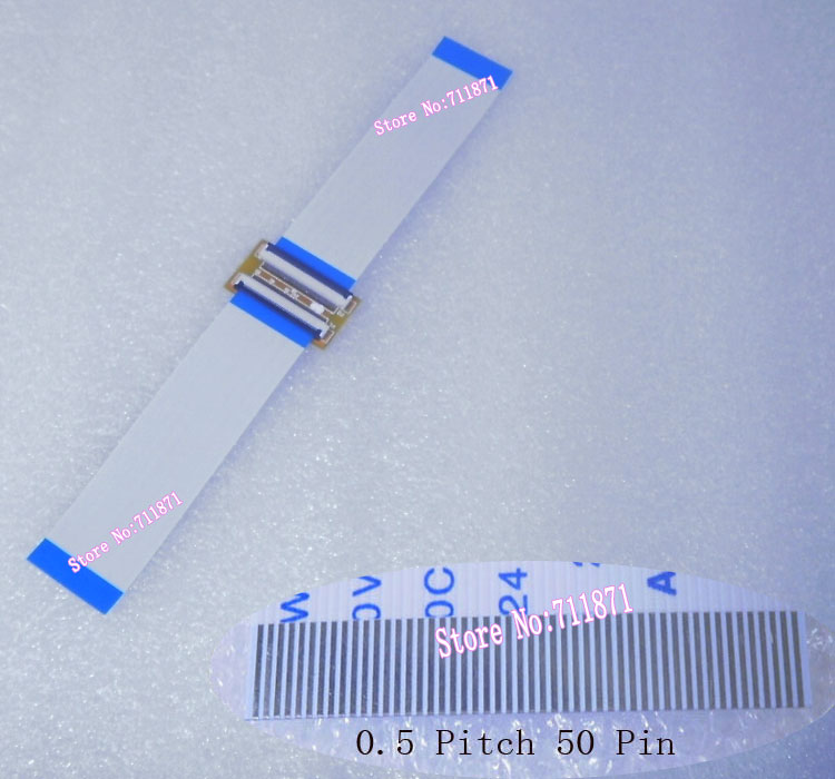
And a Adafruit 2-8 pitft capacitive touch:
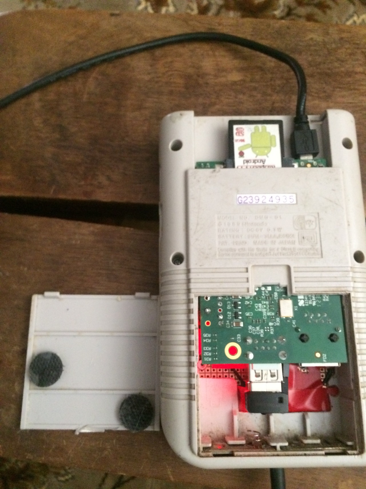
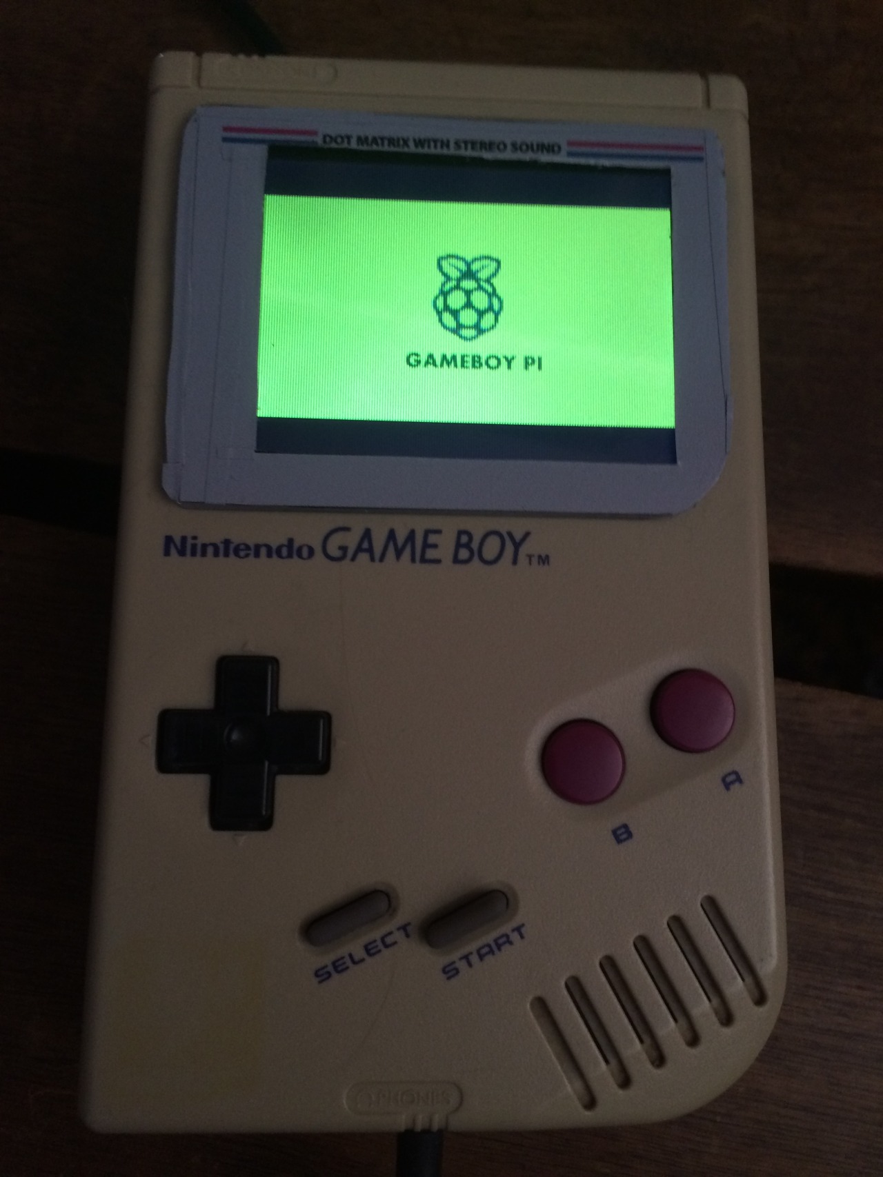
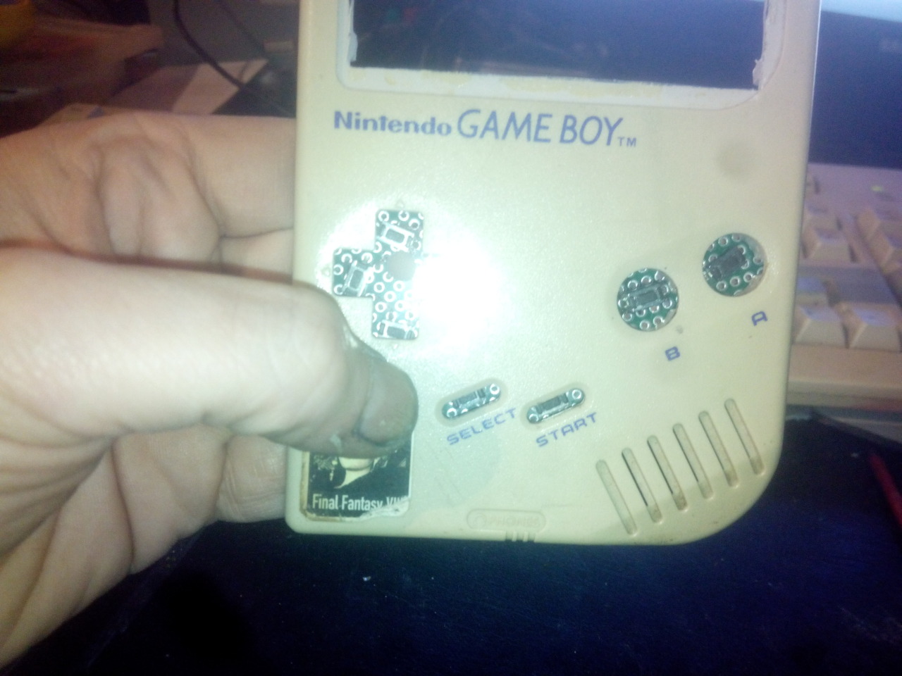
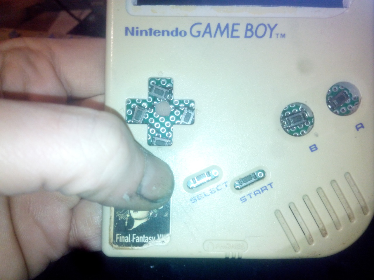
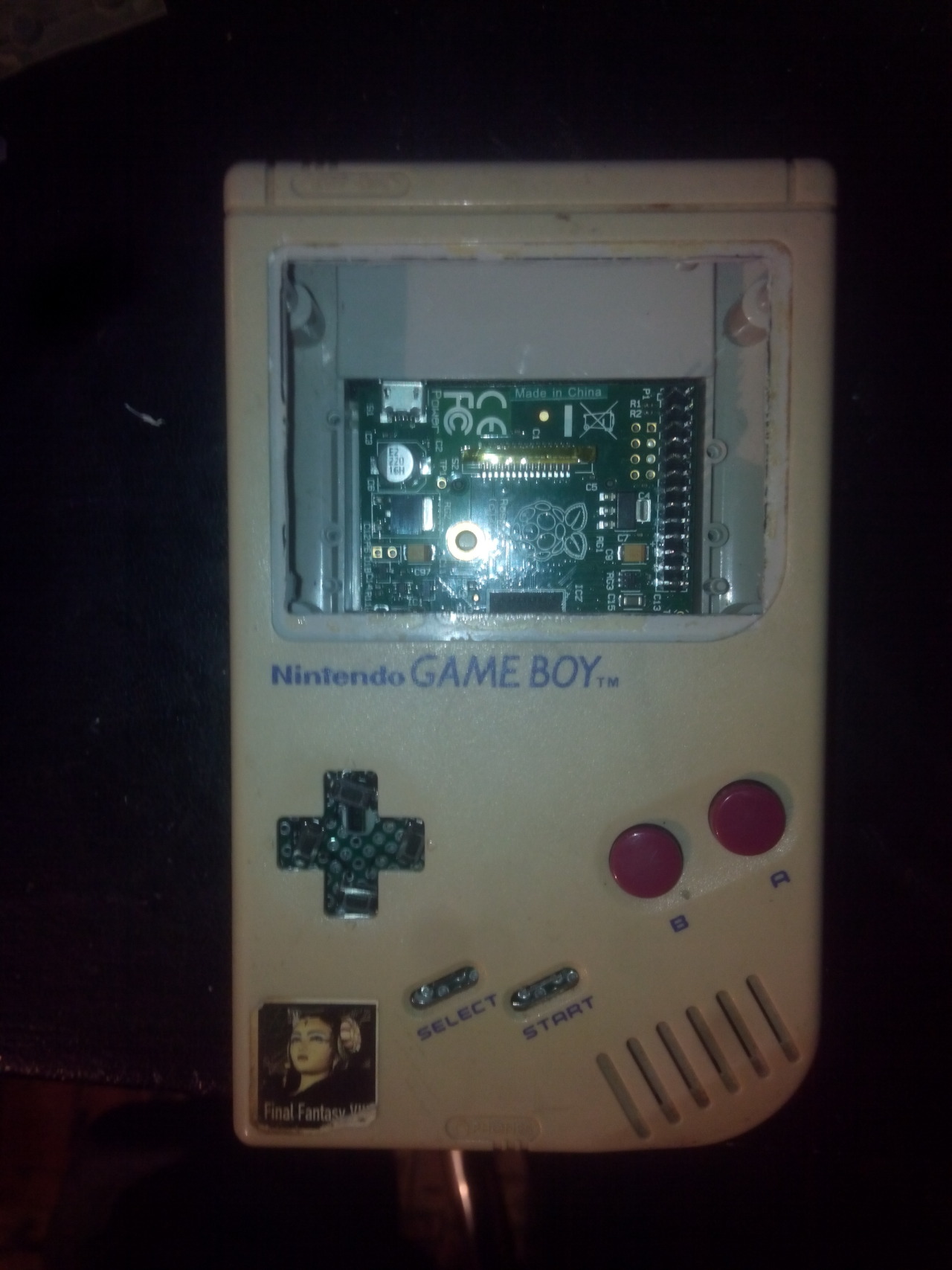
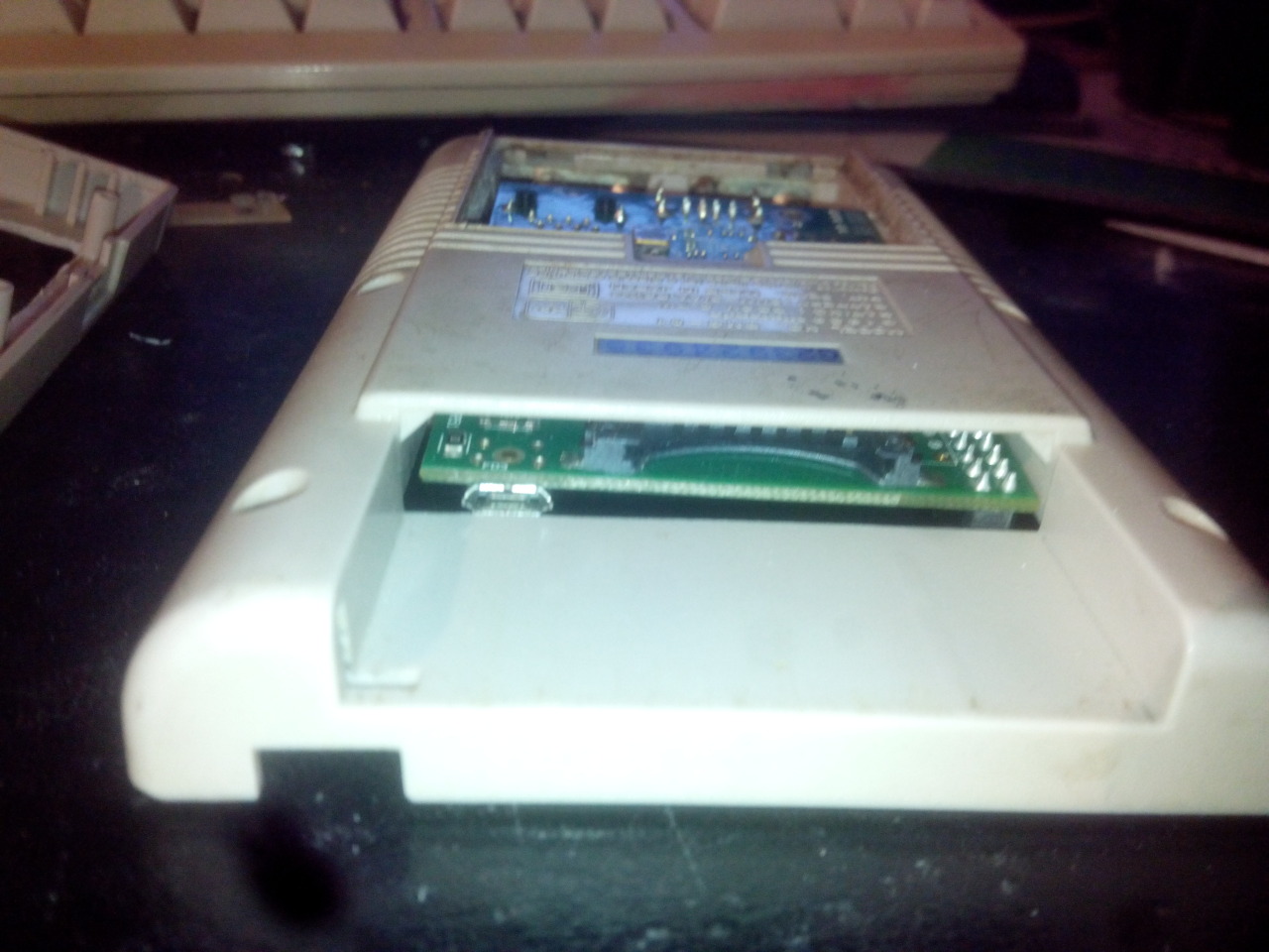
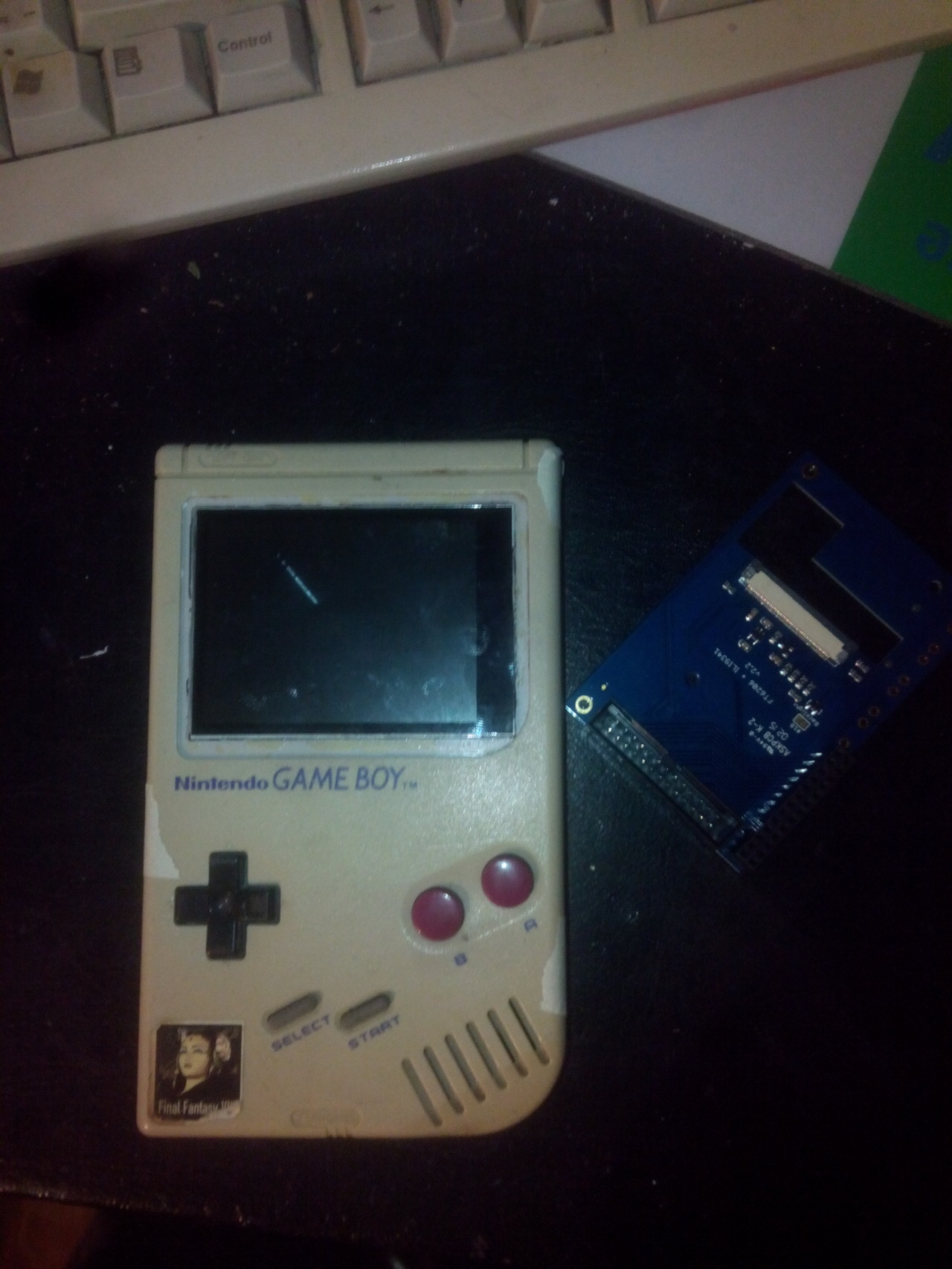
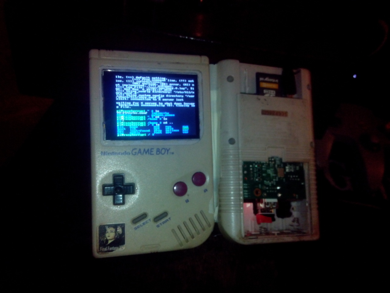
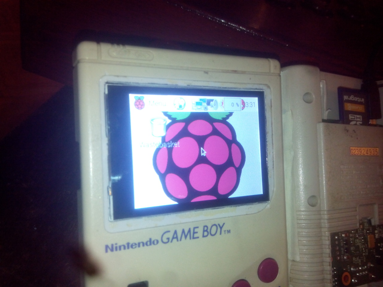
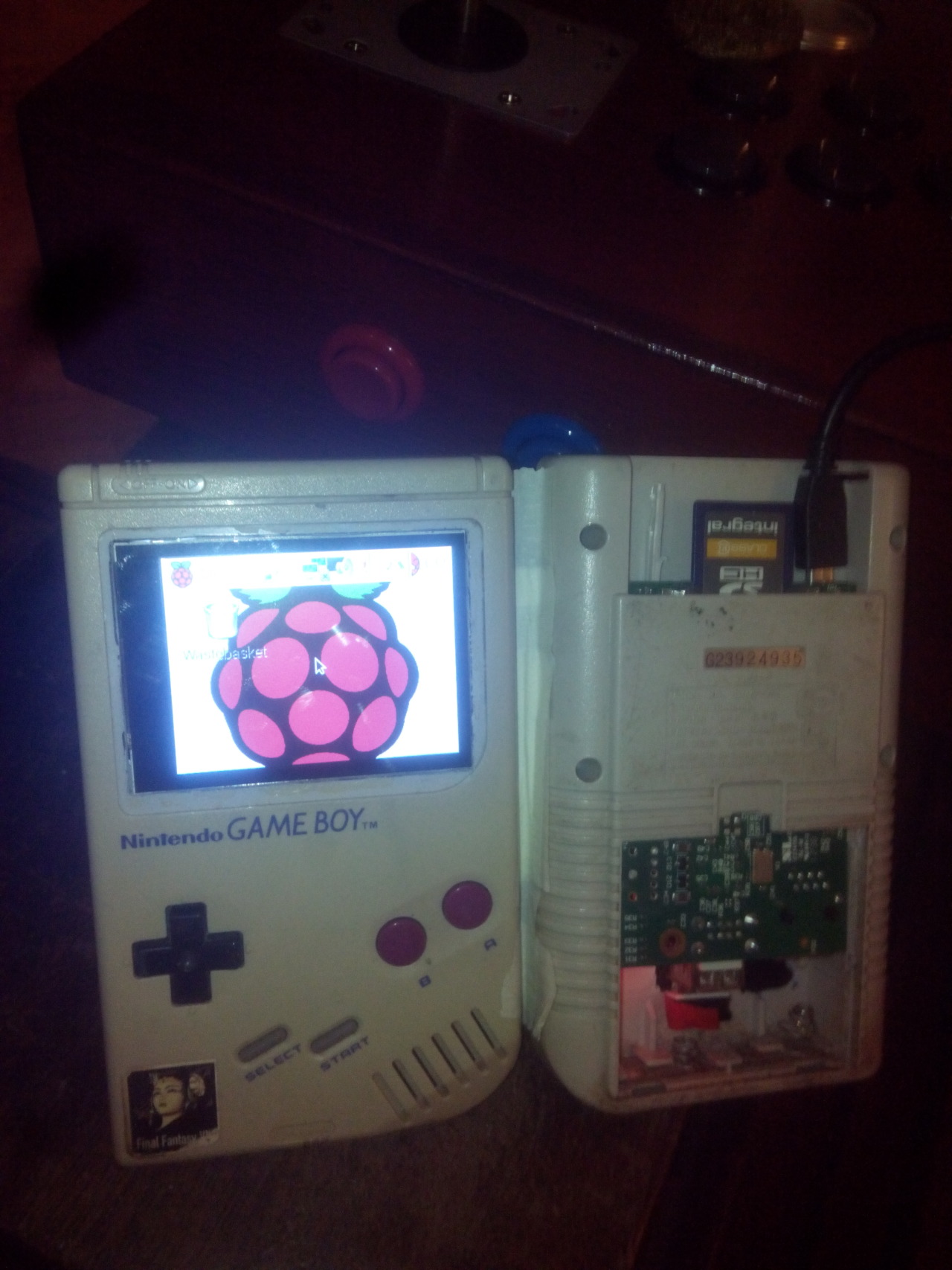
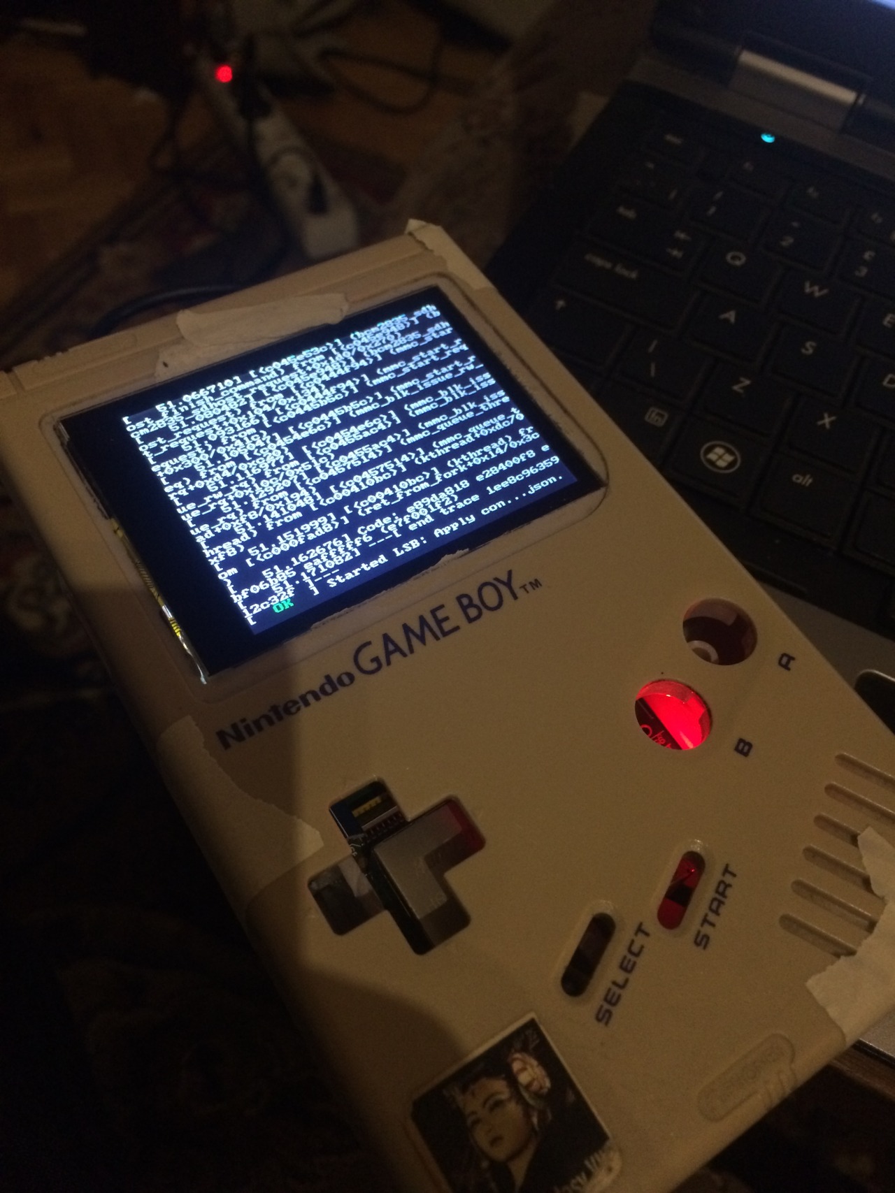
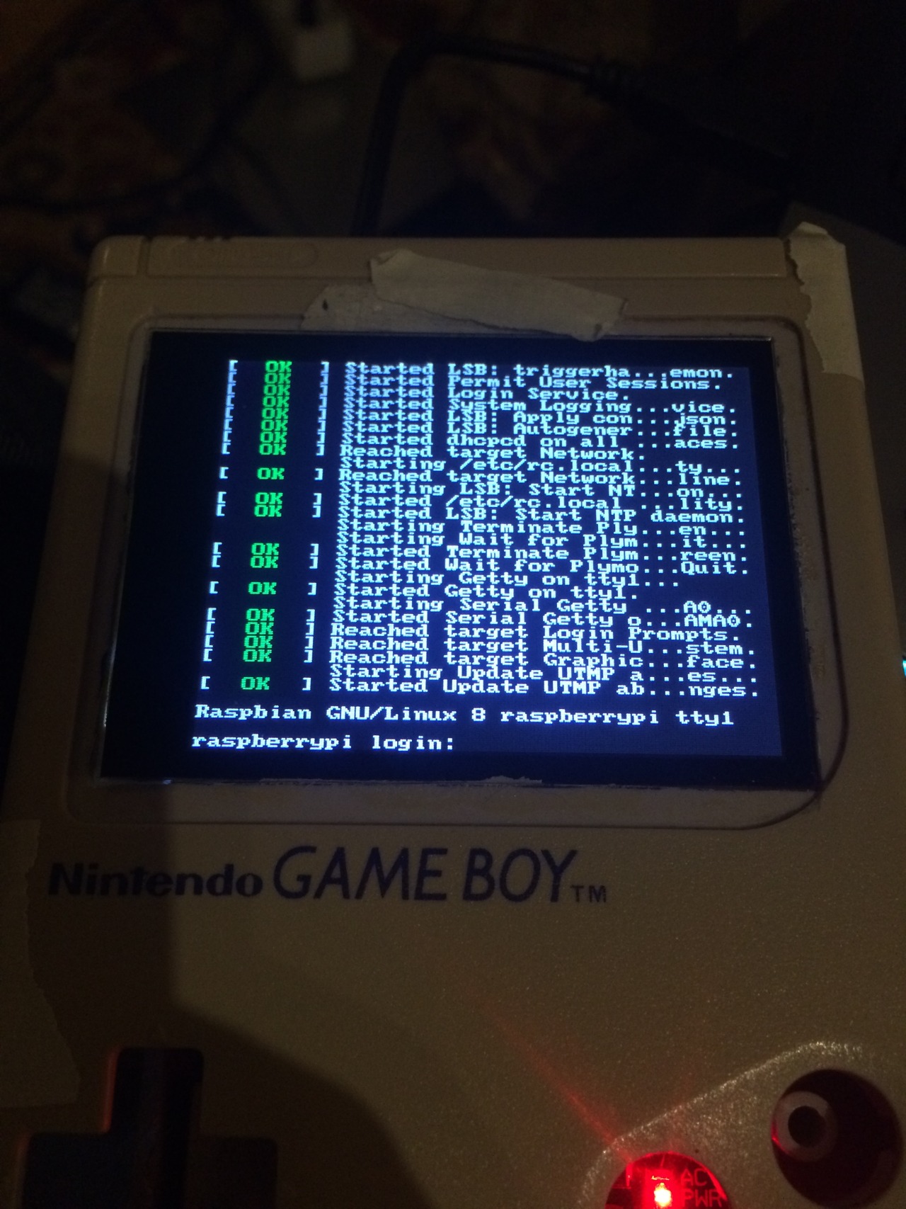
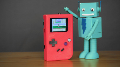
Below are some pictures of my GAMEBOY Pi that is mostly finished.
Things todo build in the speaker and power bar remove some plastic form d-pad because its fits to well…
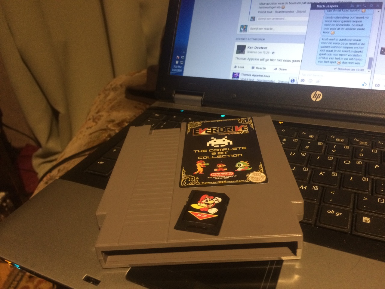
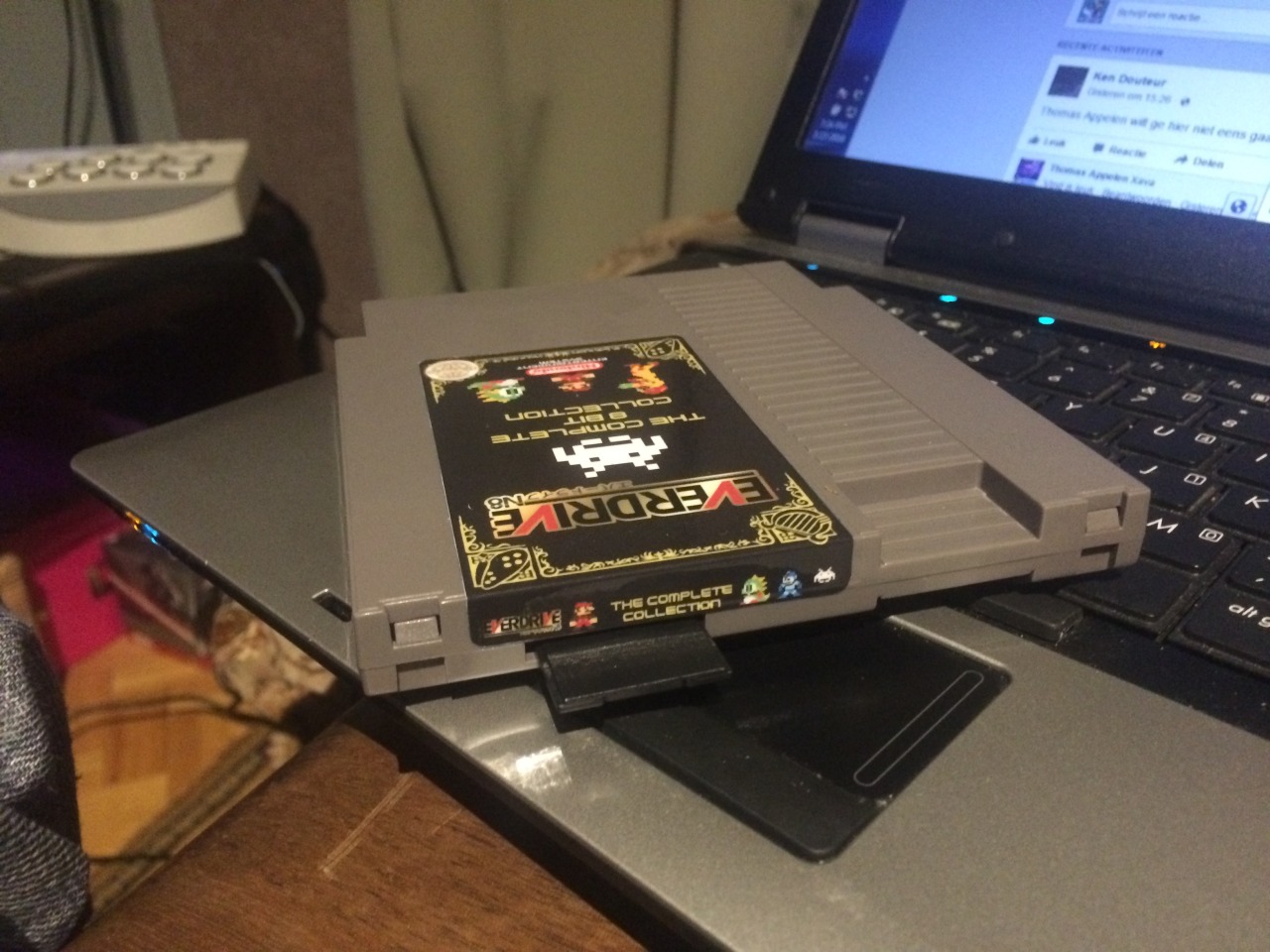
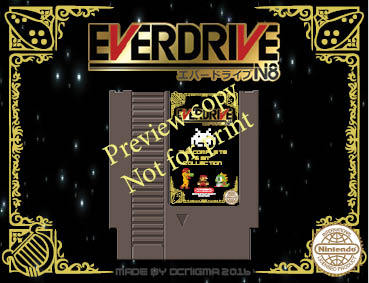
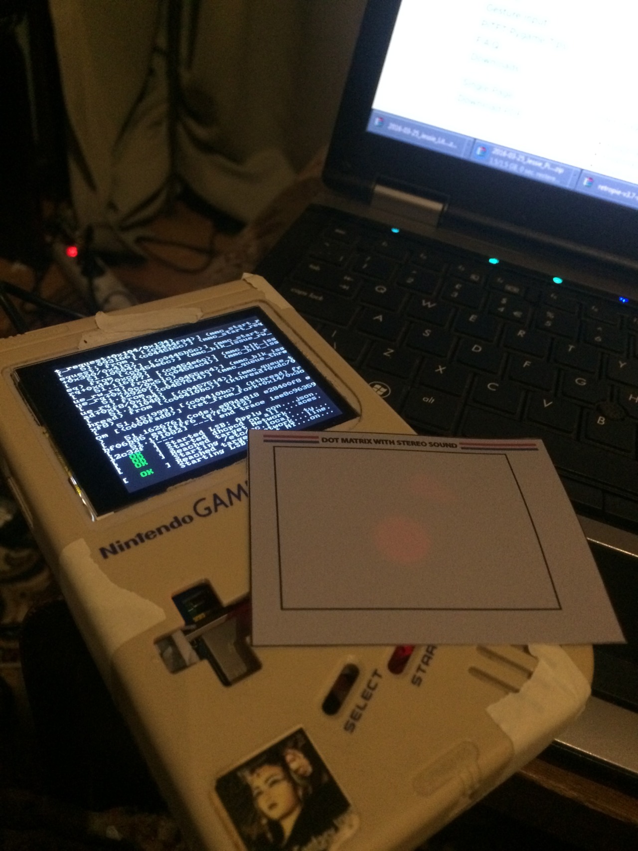
But thinking of making a custom cartridge to slide in to the slot of the Gameboy.
 (not my Picture just for show my version will have a power-bar also. How? wait and see )
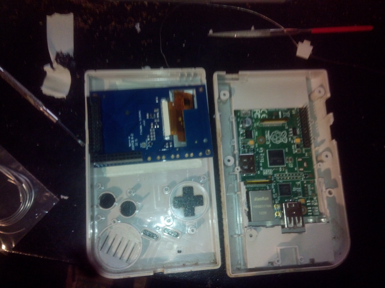
Build in Wifi and dongle for keyboard for now, in the future I gone extend one port to the side.
Ethernet is still available but don’t use a High-end cables, my own made utp cable works perfect 🙂
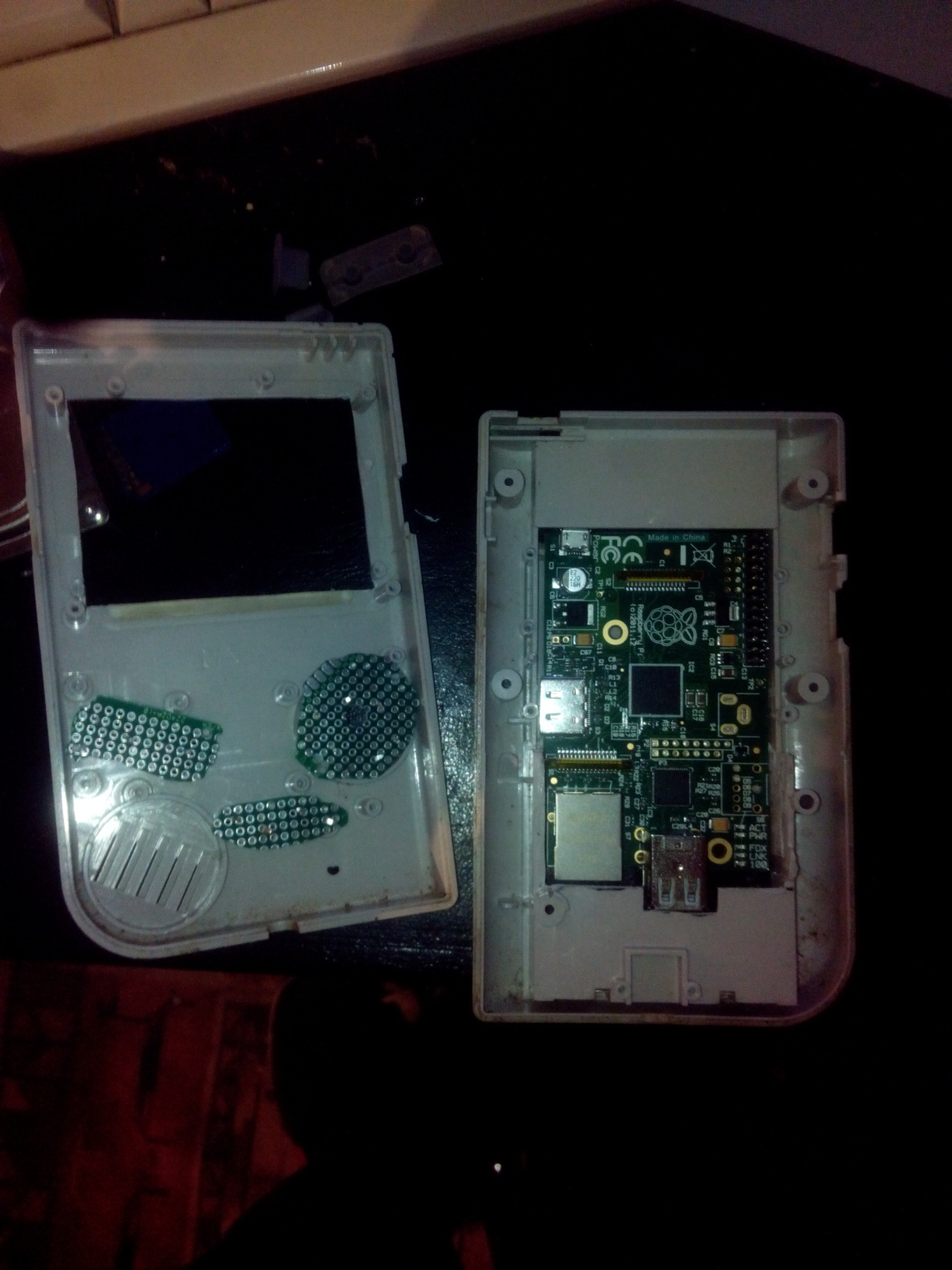
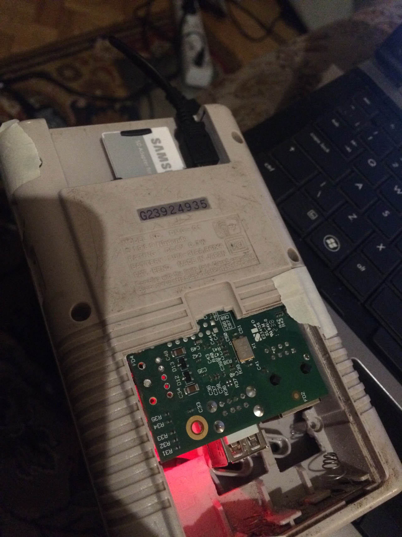
conversion:
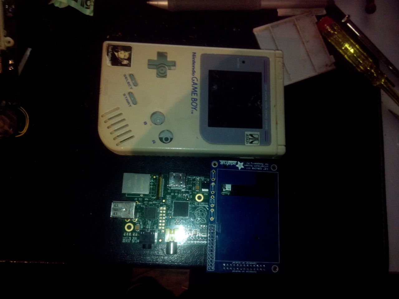
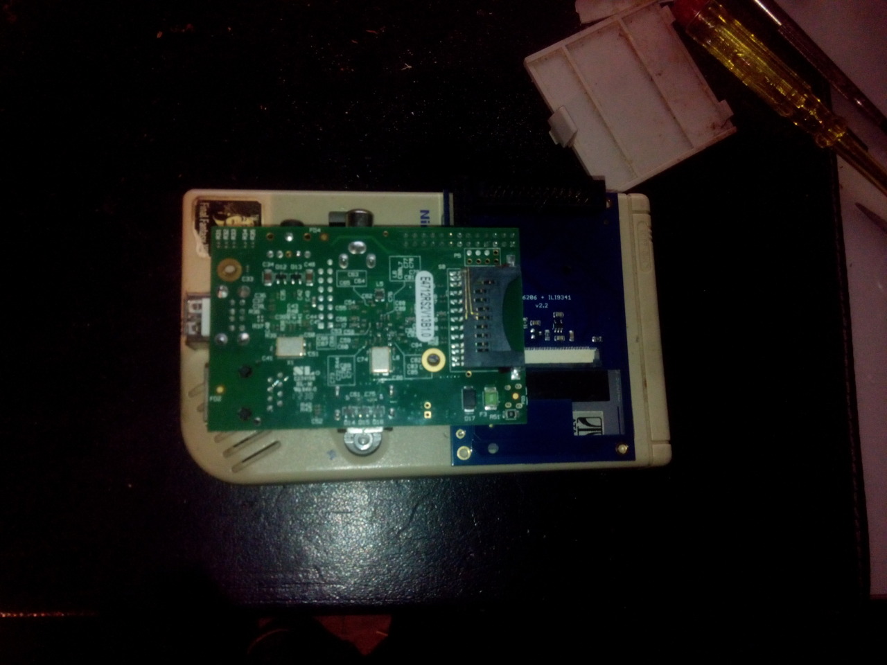
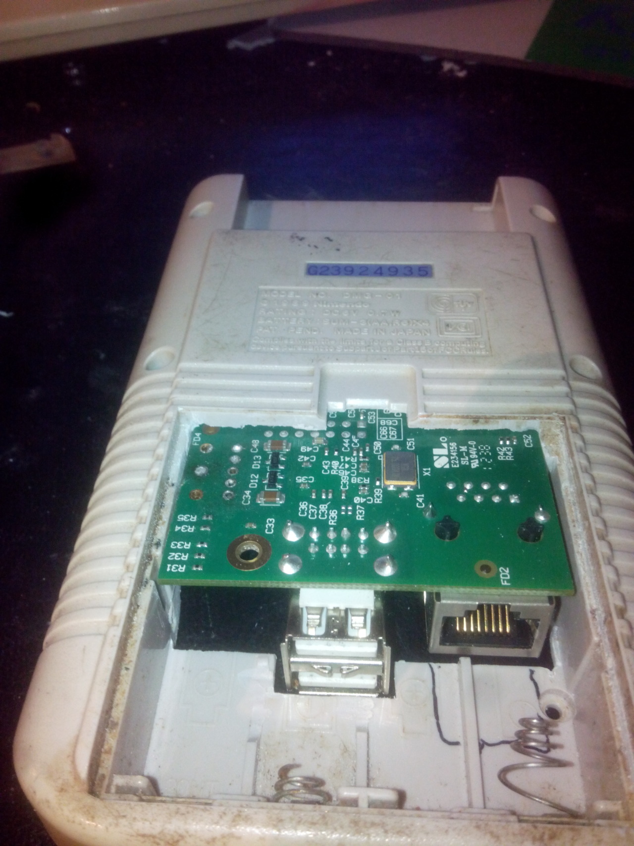
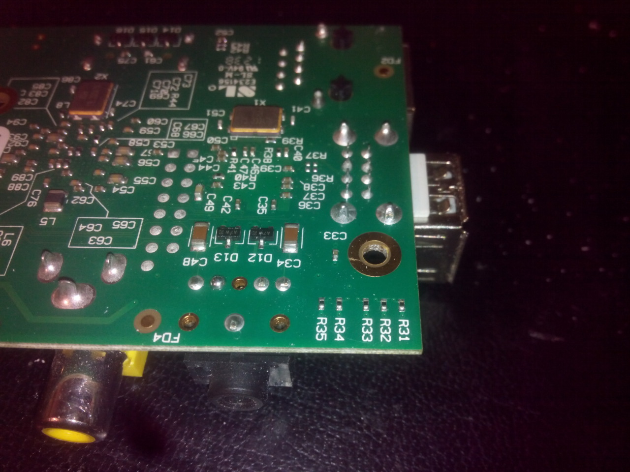 Problem Video out and speaker jack are on the wrong side. Need to de-solder them.
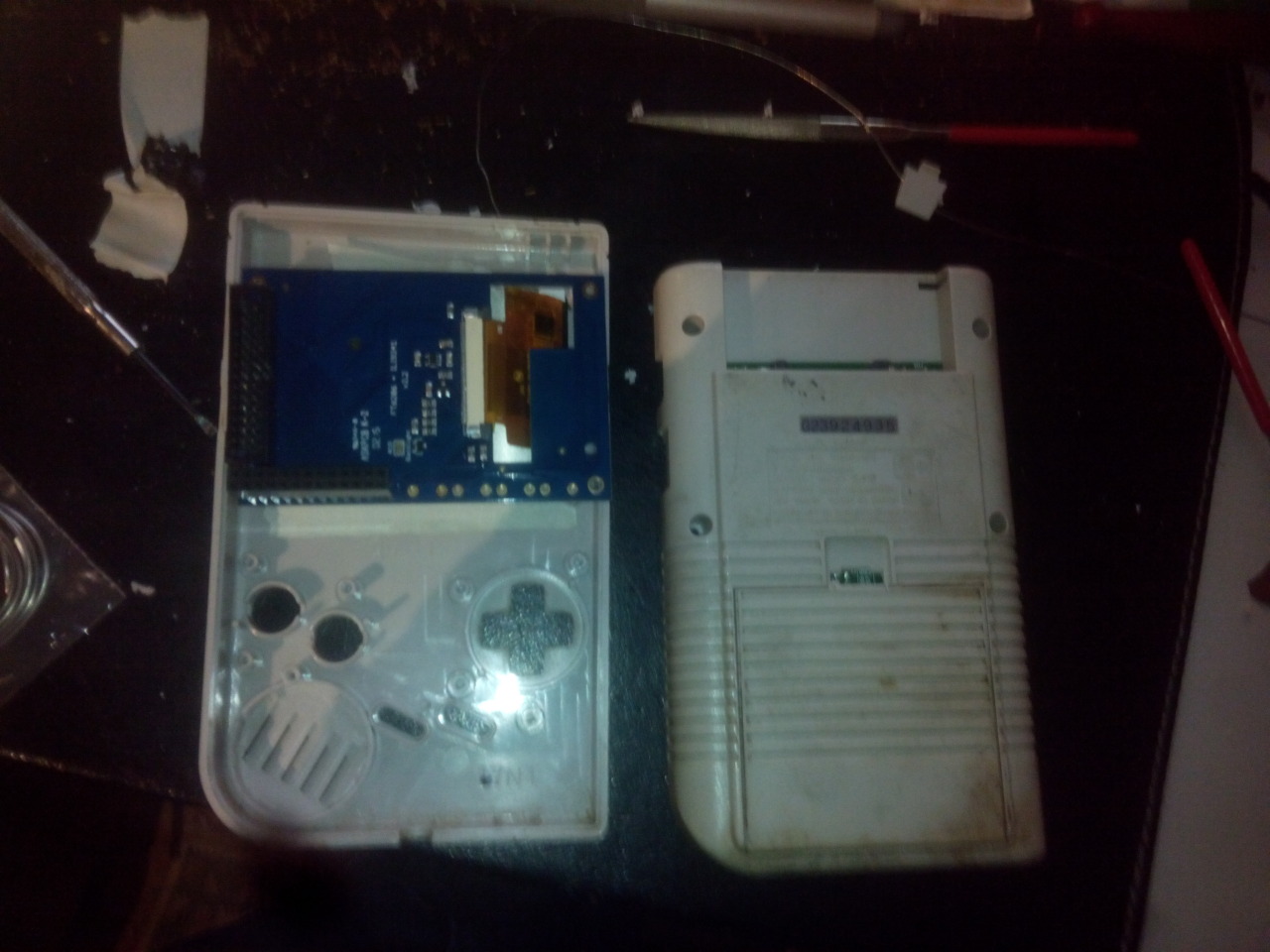
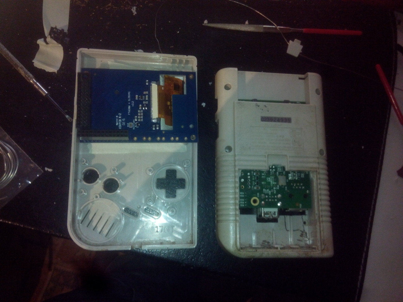
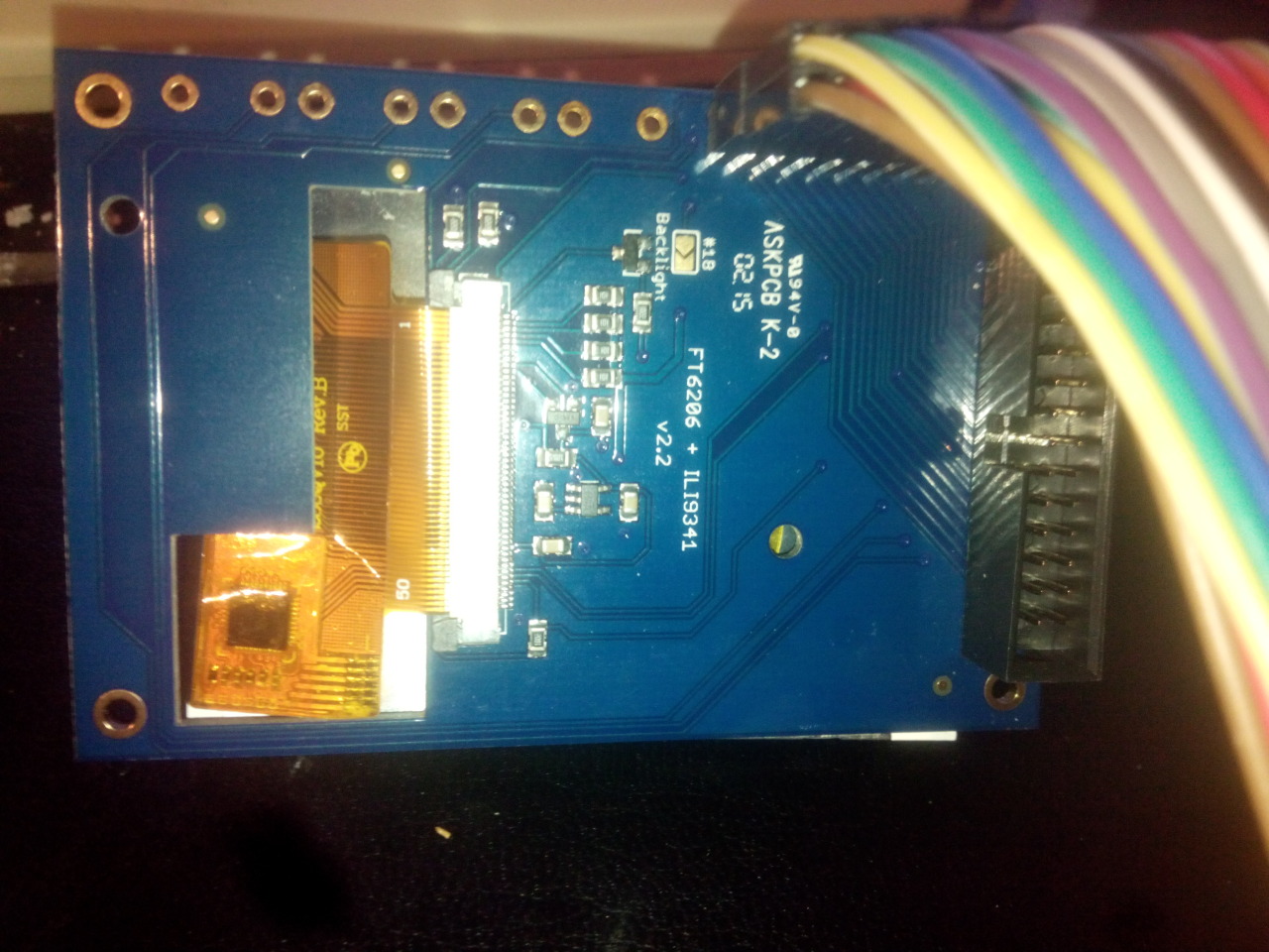 PiTFT pcb is to big for the Gameboy case need to chip it down.
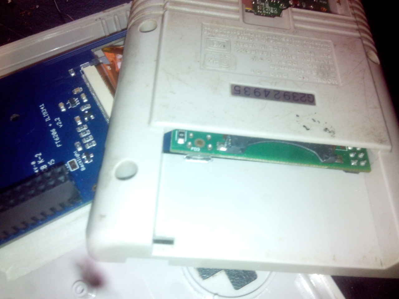

I started this project awhile back so if you want to do this. Do little things, one thing at the time.
Don’t start doing lots of things at once because in the end you will need to change or rework it again…
(Tip from Ben Heck and now from me 😀 )


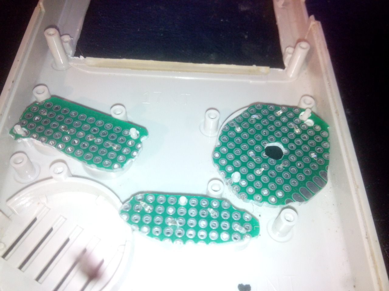
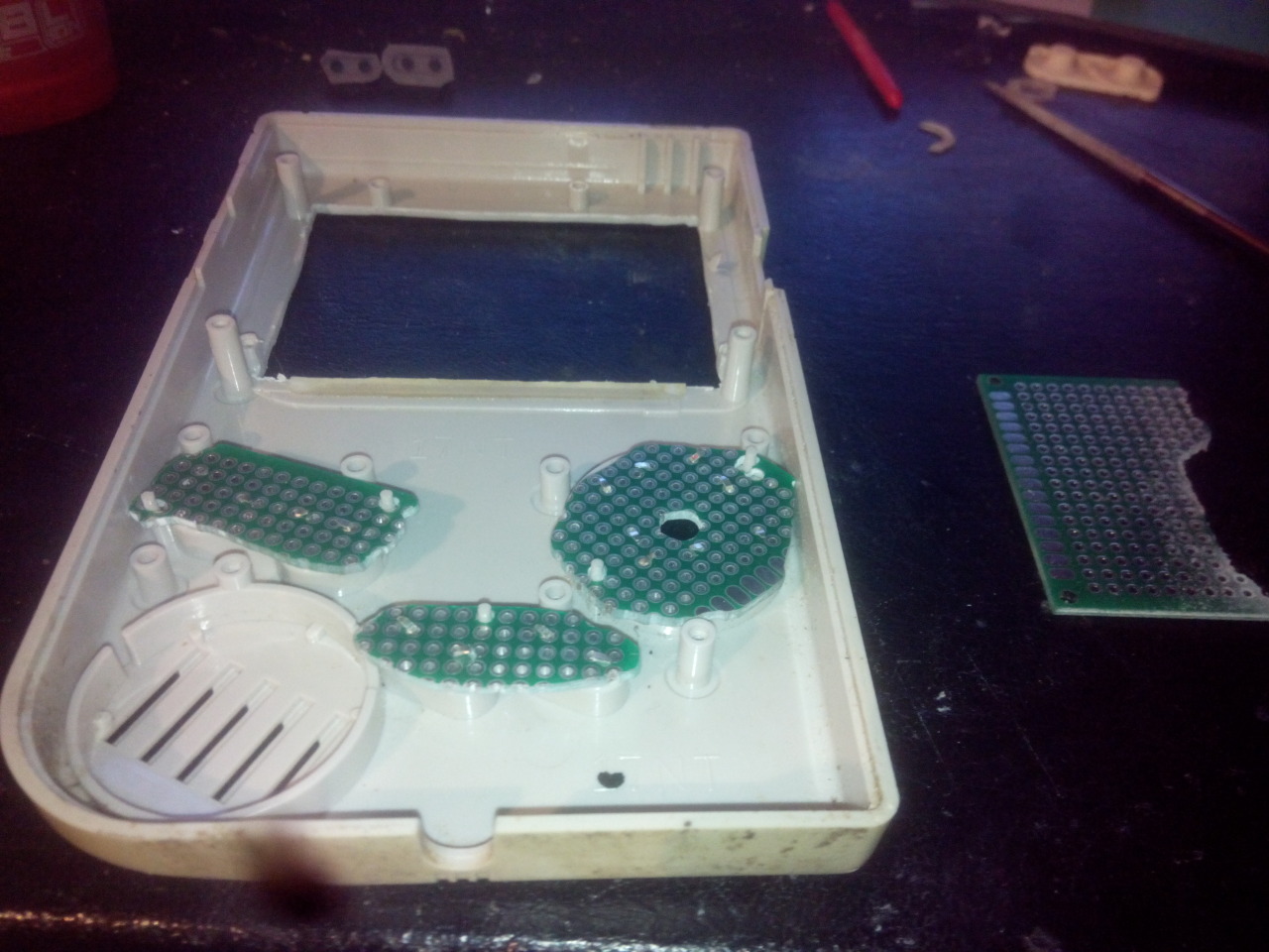
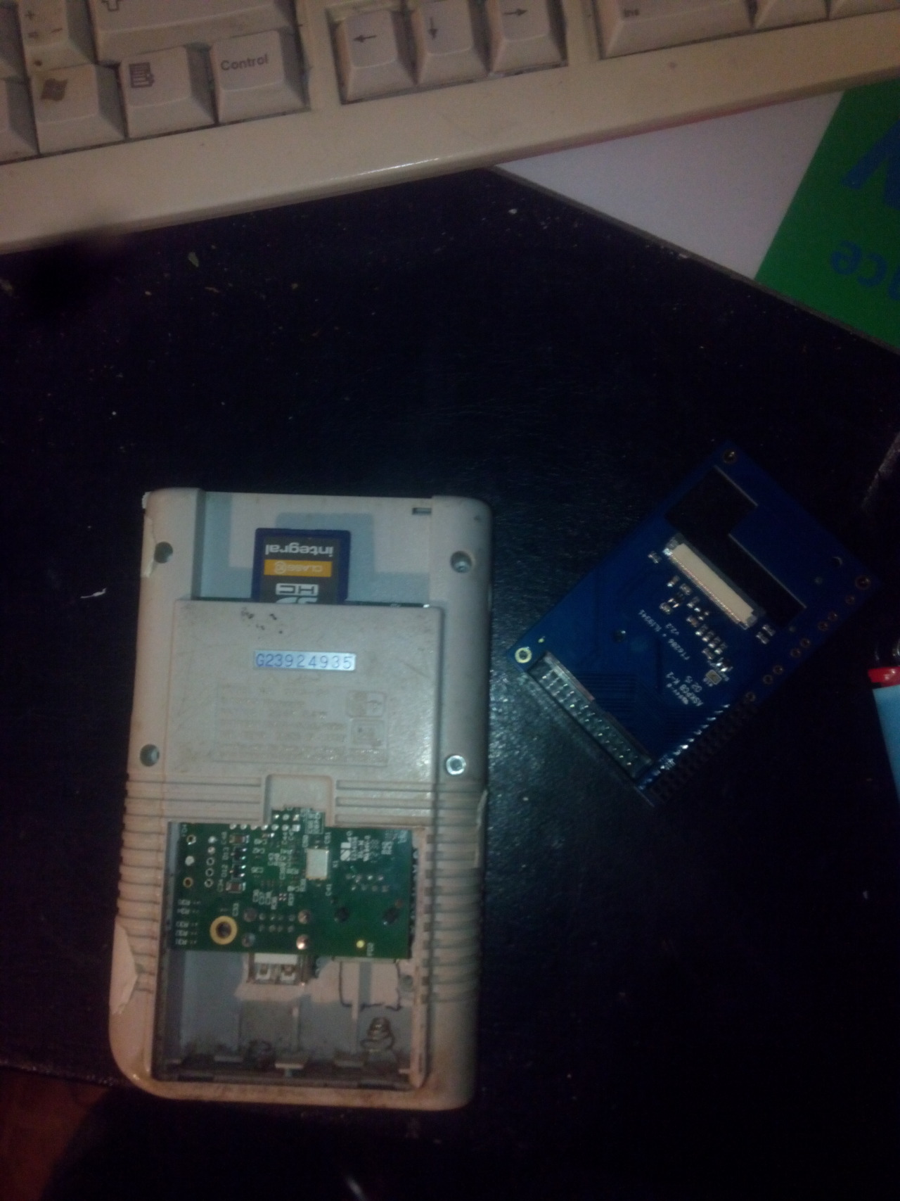
 I have rebuild the pcb for the controls because this way its much stronger then before. And the board looks more like the original Gameboy PCB haha.
RetroPi and PiTFT and DIY Joystick test!
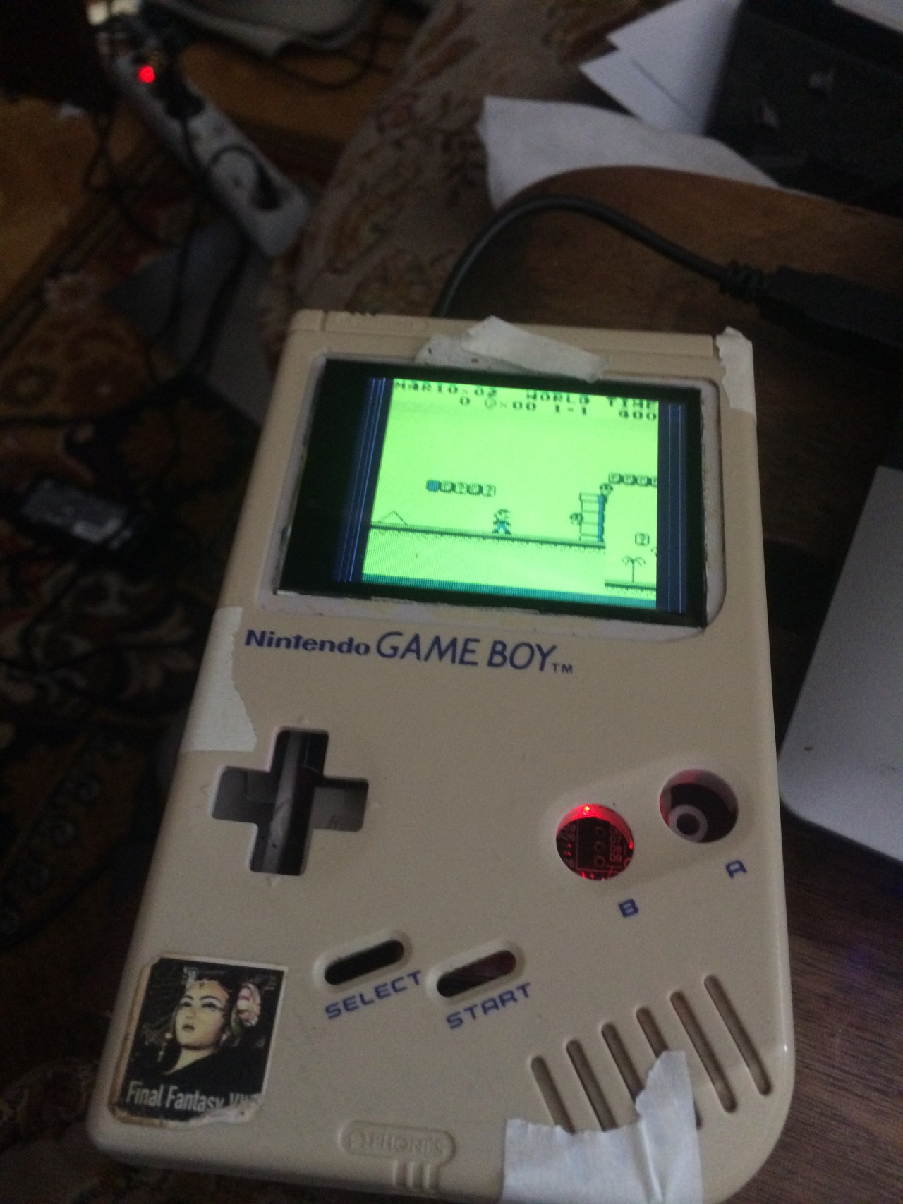
Testing the tact switches…
RetroPi and PiTFT and DIY Joystick test 2!
More testing of the tact switches… 😀 Mario is fun hahaha.
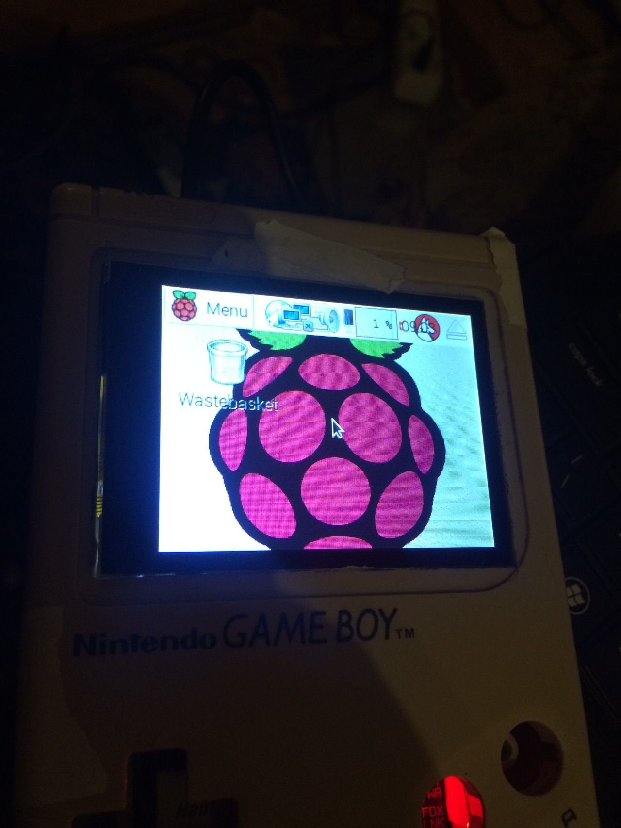
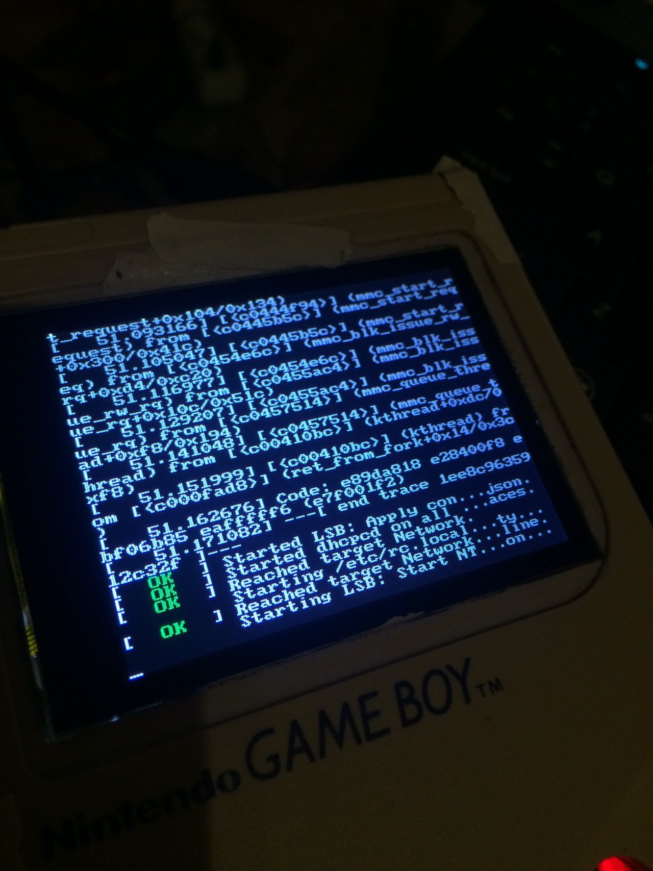
For those how notice i have some strange glitching in my screen in the video’s above.
This is because at that time my raspberry pi setup was not perfect. Not that its now LOL.
But the screen glitching is gone…
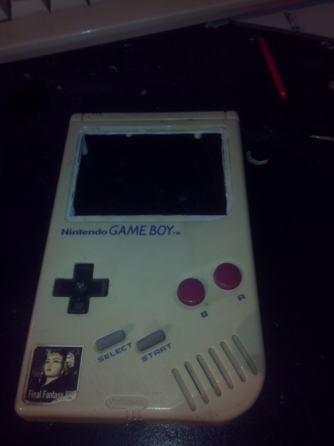
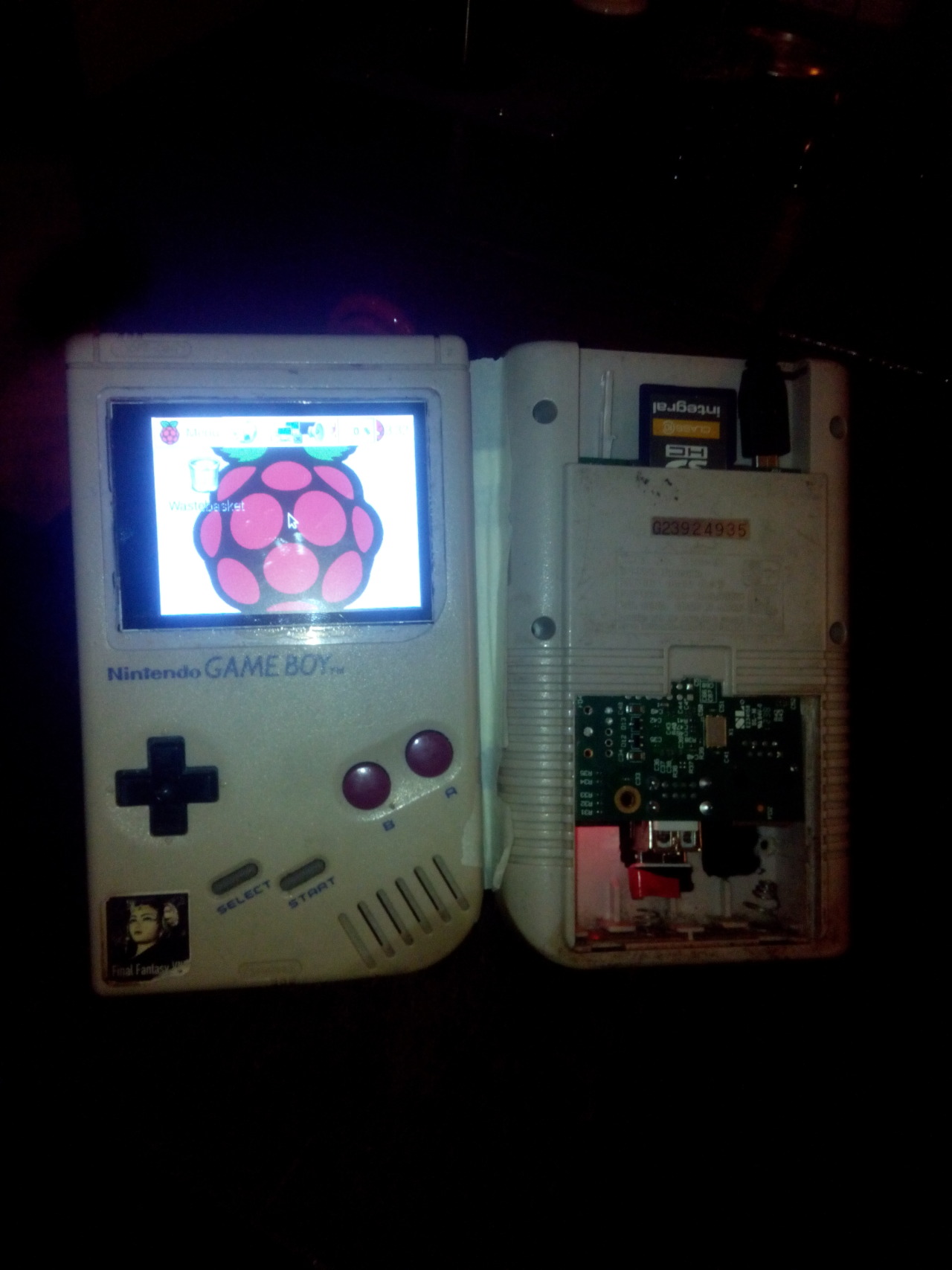
GAMEBOY PI Semi complete Test!
This is my last video i made for now showing it closed (taped down) and using the original GAMEBOY buttons on my custom pcb using those 8 tact switches.
If I have time i will make a new video showing it closed with screws and without glitches in the screen.
This install will take about 1,5 hours
First download the 2016-03-25-28c.img.
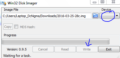
Make sd img from 2016-03-25-28c.img
sudo apt-get update && sudo apt-get upgrade
sudo apt-get install -y git dialog
cd /~/
git clone –depth=1 https://github.com/RetroPie/RetroPie-Setup.git
cd RetroPie-Setup
chmod +x retropie_setup.sh
sudo ./retropie_setup.sh
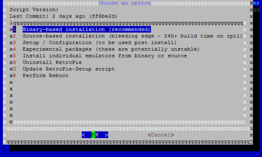
Install binary-based installation. (get cup of coffee or something)
in case kernel crash. happen to my a few times…..
(Reason a faulty usb power device…. raspberry don’t like)
sudo dpkg –configure -a
then
sudo apt-get autoremove
And try again… when successful exit don’t reboot.
sudo apt-get install cmake
sudo apt-get install libbsd-dev
Create file: /usr/share/X11/xorg.conf.d/99-fbdev.conf
sudo nano /usr/share/X11/xorg.conf.d/99-fbdev.conf
add in nano
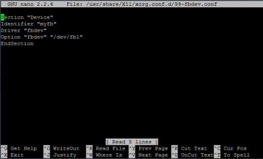
Identifier “myfb”
Driver “fbdev”
Option “fbdev” “/dev/fb1”
EndSection
Close Nano and Save ( CTRL+X, Yes, ENTER)
cd .. ( goto home cd /~/ will do just fine)
git clone https://github.com/AndrewFromMelbourne/raspi2fb
cd raspi2fb/
mkdir build
cd build
cmake ..
make
sudo make install
sudo cp ../raspi2fb@.service /etc/systemd/system/
sudo systemctl daemon-reload
sudo systemctl enable raspi2fb@1.service
sudo systemctl start raspi2fb@1
Almost done:
sudo dpkg-reconfigure console-setup
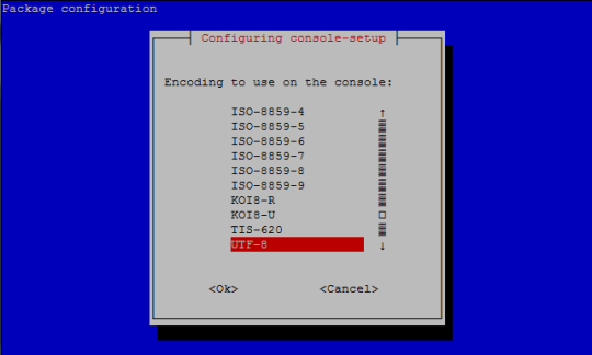 Select “UTF-8”, “Guess optimal character set”, “Terminus” and “6×12 (framebuffer only).”
sudo nano /boot/config.txt
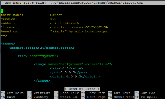
sudo nano /etc/emulationstation/themes/carbon/carbon.xml
Close Nano and Save ( CTRL+X, Yes, ENTER)
sudo reboot
And check if everything is still working if you want to add your own controls continue below

cd /~/
git clone https://github.com/adafruit/Adafruit-Retrogame
cd Adafruit-Retrogame
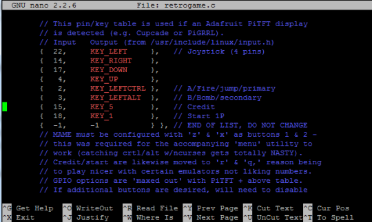
Edit the file retrogame.c, looking for the table called ioStandard and the input.h table. Each line in brackets represents one pin on the GPIO header and a corresponding key code.
The full list of available keycodes can be found in /usr/include/linux/input.h
My setup:
// Input Output (from /usr/include/linux/input.h)
{ 22, KEY_LEFT }, // Joystick (4 pins)
{ 14, KEY_RIGHT },
{ 17, KEY_DOWN },
{ 4, KEY_UP },
{ 2, KEY_LEFTCTRL }, // A/Fire/jump/primary
{ 3, KEY_LEFTALT }, // B/Bomb/secondary
{ 15, KEY_5 }, // Credit
{ 18, KEY_1 }, // Start 1P
{ -1, -1 } }, // END OF LIST, DO NOT CHANGE
You’ll need to be careful in your GPIO pin selection…some are used by the PiTFT display, others have certain reserved functions. Any green GPIO pin is free to use…yellow pins may be okay with additional setup. If you’ve configured a tactile button on the PiTFT for shutdown, that pin is unavailable for game controls.
One wire from each button connects to a GPIO pin, while the other wire connects to an available ground pin (GND). The 2.8″ PiTFT boards have an extra header breakout for the first 26 pins…for the remaining pins, you’ll need to get clever with female jumper wires on the exposed part of the Raspberry Pi GPIO header.
That is why i disable I2C and Serial so i can use gpio 2, 3, 14 and 15. Made a mistake and was easier to use gpio 14 and 15 instead. otherwise i would only disable I2C…

After editing, compile and install the code with:
make retrogame
sudo mv retrogame /usr/local/bin
Test fist before making something boot that is not working.
sudo /usr/local/bin/retrogame &
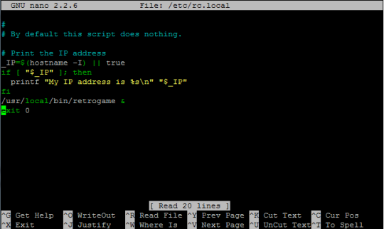
sudo nano /etc/rc.local
Reboot and you should now have “virtual” keys associated with GPIO buttons.
Or make it more fancy:
sudo nano /boot/cmdline.txt
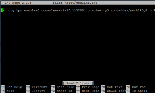
Adding a splash screen can be done from in retropie so this is optional. but this way you know what is changed in retropie to show the splashscreen at start up, same method.
Custom Splash Screen for Raspberry Pi
This is a quick and dirty solution for an unanimated custom splash screen during boot.
First of all, you need to install fbi:
apt-get install fbi
Copy your custom splash image to /etc/ and name it “splash.png”
example code:
sudo mv splash.png /etc/init.d/
Next, create an init.d script called “asplashscreen” in “/etc/init.d/”.
sudo nano /etc/init.d/asplashscreen
I chose “asplashscreen” with an “a” at the beginning to be sure it starts first.
#! /bin/sh
### BEGIN INIT INFO
# Provides: asplashscreen
# Required-Start:
# Required-Stop:
# Should-Start:
# Default-Start: S
# Default-Stop:
# Short-Description: Show custom splashscreen
# Description: Show custom splashscreen
### END INIT INFO
do_start () {
/usr/bin/fbi -T 1 -noverbose -a /home/pi/RetroPie/splashscreens/splash.png
exit 0
}
case “$1” in
start|””)
do_start
;;
restart|reload|force-reload)
echo “Error: argument ‘$1’ not supported” >&2
exit 3
;;
stop)
# No-op
;;
status)
exit 0
;;
*)
echo “Usage: asplashscreen [start|stop]” >&2
exit 3
;;
esac
:
Then make that script executable and install it for init mode:
chmod a+x /etc/init.d/asplashscreen
insserv /etc/init.d/asplashscreen
Reboot and watch your custom splash screen:
sudo reboot
If everything is correct you still boot in console but now is everything setup to start retropie
Start by typing:
emulationstation
After the startup you need to setup you fresh made controls by pressing one of the keys and then follow the onscreen text. Skipping by holding down one button.
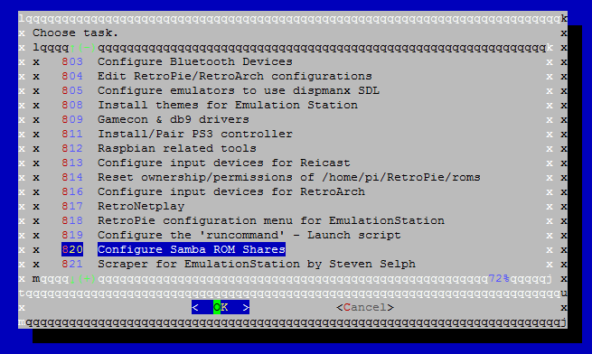
After that your done and can start adding roms, you have 2 options for this by usb or by samba.
So you probably need to set that up 2 lucky for us you can do this from in emulationstation
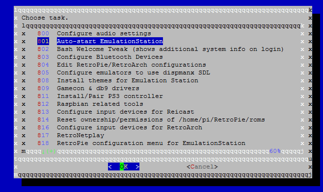
choose retropie setup from the menu.
The let it boot directly in to emulationstation.
 Next Samba: Oleee

For now i leave this project to rest, i am glad whit the progress that i made.
also after 6 months I can close the case 😀 hooray!!!
Recap of what to do:
-Fix asla error….
-Build power cartridge for power.
-Build in speaker
-Extend usb to connector port and replace it by usb.
Some progress pictures for my Gameboy Pi
Gameboy Pi install:
Make sd img from 2016-03-25-28c.img
Then install retropi:
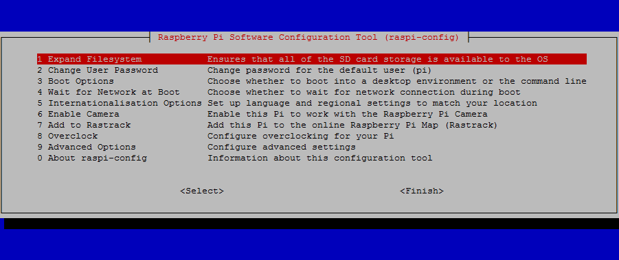
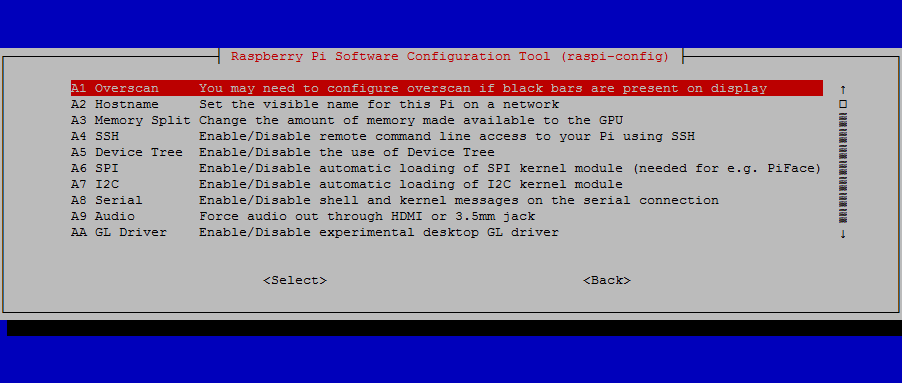
sudo raspi-config
Enable ssh
Resize SD
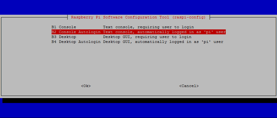
Disable boot Gui boot Console:
sudo reboot.
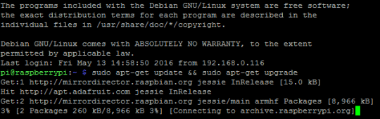
sudo apt-get update && sudo apt-get upgrade
sudo apt-get install -y git dialog
cd
git clone –depth=1 https://github.com/RetroPie/RetroPie-Setup.git
cd RetroPie-Setup
chmod +x retropie_setup.sh
sudo ./retropie_setup.sh
Install binary-based.
Install fb
sudo apt-get install cmake
sudo apt-get install libbsd-dev
Create file: /usr/share/X11/xorg.conf.d/99-fbdev.conf
sudo nano /usr/share/X11/xorg.conf.d/99-fbdev.conf
add in nano
Section “Device”
Identifier “myfb”
Driver “fbdev”
Option “fbdev” “/dev/fb1”
EndSection
Exit Nano
sudo apt-get install cmake
git clone https://github.com/AndrewFromMelbourne/raspi2fb
cd raspi2fb/
mkdir build
cd build
cmake ..
make
sudo make install
sudo cp ../raspi2fb@.service /etc/systemd/system/
sudo systemctl daemon-reload
sudo systemctl enable raspi2fb@1.service
sudo systemctl start raspi2fb@1
TEST
sudo nano /etc/rc.local
add before exit 0
sudo systemctl daemon-reload
sudo systemctl enable raspi2fb@1.service
sudo systemctl start raspi2fb@1
END TEST
sudo dpkg-reconfigure console-setup
Select “UTF-8”, “Guess optimal character set”, “Terminus” and “6×12 (framebuffer only).”
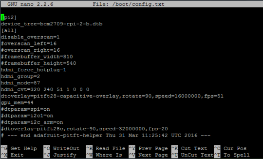
sudo nano /boot/config.txt
Add
framebuffer_width=810
framebuffer_height=540
hdmi_force_hotplug=1
hdmi_group=2
hdmi_mode=87
hdmi_cvt=320 240 51 1 0 0 0
dtoverlay=pitft28-capacitive-overlay,rotate=90,speed=80000000,fps=51
gpu_mem=44
sudo nano /etc/emulationstation/themes/carbon/carbon.xml
fontSize to 0.05
Controls
cd
git clone https://github.com/adafruit/Adafruit-Retrogame
cd Adafruit-Retrogame
Edit the file retrogame.c, looking for the table called ioStandard (not the ioTFT table — that’s for other projects). Each line in brackets represents one pin on the GPIO header and a corresponding key code.
The full list of available keycodes can be found in /usr/include/linux/input.h
raspberry_pi_retrogame.png
After editing, compile and install the code with:
Copy Code
make retrogame
sudo mv retrogame /usr/local/bin
To make retrogame start automatically when the system boots:
Copy Code
sudo nano /etc/rc.local
Before the final “exit 0” line, insert this one line:
Copy Code
/usr/local/bin/retrogame &
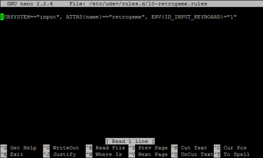
Just one more file needs editing, so that EmulationStation recognizes retrogame as a keyboard:
Copy Code
sudo nano /etc/udev/rules.d/10-retrogame.rules
Copy and paste this line exactly into the new file:
Copy Code
SUBSYSTEM==”input”, ATTRS{name}==”retrogame”, ENV{ID_INPUT_KEYBOARD}=”1″
Reboot and you should now have “virtual” keys associated with GPIO buttons.